There are two parts to the In-Lab assignment: a simpler version
(Robbie) to be done in schematic and HDL form as well as a more complex
version (Renee) to be done only in HDL (the schematic version would be
very complex).
- The combinational Verilog reference, found on the lab webpage, will be needed.
- Generally, see Chapter 2 and section 6.2 of Vahid.
- Understanding comparators may also be helpful. See sec 4.5 of
Vahid.
- Module declarations.
- Declaring parameters as input or output.
- Declaring variables as wires.
- Instantiating other modules.
- Using assign statements. These assign statements may include only the operators AND (&), OR (|), XOR (^), and NOT(~). You may not use any other operators (such as ">", "<, and "?:").
- Robbie the Robot
- He is to go straight if the forward sensor detects the beacon or both the left and the right sensors detect the beacon.
- If only the right or left sensor detects the beacon, he should go in the the direction of the active sensor.
- If the forward beacon is on and a left or right beacon is on, he should go forward.
- Otherwise, he is to stop.
- Renee the Robot
- Beacon sensors:
Renee uses two sophisticated sensors in place of Robbie's three simple sensors. The two sensors are aimed at Renee's left and right (in the same places as Robbie's left and right sensors). Unlike Robbie's sensors, however, Renee's sensors provide information about how strong of a signal they are getting from the beacon. The sensors return a 3-bit unsigned number. The closer the beacon (and more toward the center of the cone of a given sensor) the higher the value they return. - Bumper sensors:
Renee has four of these: one each on the front, left, right and back. They are active low: they return a "0" if Renee has bumped into something in that direction, and a "1" if she has not. - Wheels:
Renee's wheels can go forward and backward, as well as stop. She can now perform the following actions (though you may not need to do all these actions...):Action Left Wheel Right Wheel Forward F F Left S F Right F S Stop S S Left Back S R Right Back R S Reverse R R
Table 1: How Renee uses her wheels to perform her actions.
- If her front bumper sensor is the only one detecting a collision, she should move in reverse.
- If her back bumper sensor is the only one detecting a collision, she should move forward.
- If her left bumper sensor is the only one detecting a collision, she should move right back.
- If her left and front bumper sensors are the only ones detecting a collision, she should move right back.
- If her right bumper sensor is the only one detecting a collision, she should move left back.
- If her right and front bumper sensors are the only ones detecting a collision, she should move left back.
- If her left and back bumper sensors are the only ones detecting a collision, she should move right.
- If her right and back bumper sensors are the only ones detecting a collision, she should move left.
- If any two bumper sensors on opposite sides are detecting a collision (front and back or left and right), she should stop.
- The bumper sensors should be treated as detecting a collision if the corresponding key is pressed. (Recall that the Keys are active low.)
- You need to use slide swiches with Labsland because you can't hold a more than one pushbutton depressed.
- For outputs you should again use HEX0 (right wheel) and HEX1 (left wheel), displaying an "F", an "S" or an "r" (r is displayed by having segments 4 and 6 lit).
- Again, you may only use the same subset of Verilog that was allowed for Robbie.
Robbie is the simpler robot which is attempting to drive to the beacon and stop. Robbie has three sensors and two independently controlled wheels. The sensors are mounted on the front, front-right and front-left of the robot, as seen in Figure 1. These sensors detect if the beacon is in a certain area (the cones indicated in Figure 1). If the sensor does detect the beacon it outputs a "1", otherwise it will output a "0".
The two wheels are driven independently. If a "1" is sent to the wheel it turns forward, but if a "0" is sent to the the wheel it doesn't turn. Robbie will go straight if both wheels are turning forward, and will stop if both wheels are stopped. In addition, Robbie turns right if the left wheel is going forward while the right wheel isn't turning, and would turn left in the symmetric case (the left wheel stooped and the right wheel going forward).
Robbie should follow the following rules:
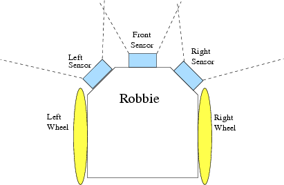
Figure 1: Robbie the robot, with sensors and wheels.
Implementation details
You are to implement Robbie twice: once using the schematic editor, and once using Verilog. Be sure to use a separate Quartus project for each implementation!Schematic version
For your schematic design, you are to use dip switches 2, 1 and 0 as the left, forward, and right sensor inputs respectively. You are to turn on the red LED #1 to indicate that the left wheel is going forward, and turn on red LED #0 if the right wheel is going forward. Otherwise those LEDs should be off.Verilog version
For this part of the assignment, you will implement Robbie entirely in Verilog. As with schematic based projects (i.e. the ripple carry adder of lab2), you can have a top-level-component and several sub-level-components. In Verilog we will refer to the components as top-level-modules and submodules. For a detailed explanation and example of Verilog modules, the hierarchical relations and connection, see the combinational Verilog reference listed with this lab (pages 1-2), which shows how a full adder is implemented in verilog with submodules.
For this part of the assignment, you will use the HEX display instead of the LEDs for your output. You should display a capital "F" on HEX0 if the right wheel is going forward, and a capital "S" if the right wheel is stopped. You should do the same on HEX1 for the left wheel. Recall that the HEX segments are active low.
Your Verilog design should be organized into a top-level-module and submodules. The top-level-module will contain Robbie's control logic, and the submodules will be used to generate the "S" and "F" patterns from the wheel control signals. The HEX display submodules should be controlled by a single bit control. For example, control bit on means display "F", control bit off means display "S". You may use the same submodule more than once if necessary. The top-level-module and submodules will have the general form:
module robbie(ls,fs,rs,lwd,rwd); //top level module declarationAs with schematic-based projects, the top-level-module must have the same name as the project. Also, the file name should have the same name as the top-level-module. The top-level-module and submodules may be placed in the same file, in this case robbie.v. FPGA pin assignments are made to the top-level-module's input and output names.
input ls,fs,rs; //input declarations
output [6:0]lwd,rwd; //output declarations. The notation [6:0]lwd, rwd means lwd and rwd consist of a set of
//7 connections, 6 thru 0. Each connection can be refered to individually or as a set. For example,
//assign lwd[6] = 0 sets this connection to logical 0. assign lwd = 7'h11 sets lwd[0] to logical 1,
//lwd[4] to logical 1, and all other bits to logical 0.
//For more on this, see the combinational verilog reference.
//Robbie's control logic goes here
outputSF sf1(inputs to submodule, outputs from submodule); //submodule instantiation
endmodule
module outputSF(inputs, outputs); //submodule declaration
//submodule's input and output declarations go here
//HEX display logic goes here
endmodule
Renee is similar to Robbie, but there are some significant differences. First, she has only two beacon sensors (left and right), but those sensors provide information about distance. Secondly, she has four bumper sensors (which tell her if she has hit something). Lastly, her wheels can go in reverse in addition to going forward. These changes are detailed below:
Renee should head in the direction of the sensor that indicates it has the strongest signal. If both signals are zero, Renee should stop. If the two signals are the same but not zero, Renee should go forward. However, the beacon senors are ignored if Renee has hit something: in that case her first priority is to move away from the thing she hit. If any of her bumpers detect a collision, she should follow the these rules:
Implementation details
For the Verilog design, you must use the following module declaration as your top-level module (which should be in a file named renee.v):
module renee(ls,rs,fb,rb,lb,bb,lwd,rwd);You should use the DE2 board inputs as follows:
input [2:0] ls,rs; //Beacon sensors
input fb, rb, lb, bb; //Bumper sensors
output [6:0]lwd,rwd; //wheel outputs
| Sensors | Board inputs |
|---|---|
| Right beacon sensor | SW2-SW0 (SW2 is MSB) |
| Left beacon sensor | SW6-SW4 (SW6 is MSB) |
| Left bumper sensor | Key3 (SW17 Labsland) |
| Front bumper sensor | Key2 (SW16 Labsland) |
| Back bumper sensor | Key1 (SW15 Labsland) |
| Right bumper sensor | Key0 (Sw14 Labsland) |
Table 2: Mapping of sensors to switches for Renee.
Notes:
- Drawing a truth table for Renee is pretty much impossible. There are 10 inputs (6 bits from the beacon sensors, 4 from the bumper sensors). That would give you more than 1,000 rows. So your design will have to be more ad hoc. However, you may want to draw a truth table for certain parts (say the bumpers).
- For Renee you could just write logic equations for each output directly, but that will make things very difficult. Instead you should consider writing equations for intermediate results and then using those to generate the correct results. Think carefully about what intermediate results you want. This decision will have a huge impact on how difficult the lab is. Think about how _you_ would figure out what the outputs should be if you were presented with the 10 input bits.
- For Renee you should probably use a submodule to manage your HEX displays, as we required for Robbie.
- The HEX display modules for Robbie and Renee are quite short. Because we don't allow conditionals in this lab (if statements), you are forced to write logic equations for each segment. For Robbie you can do the logic for each segment with only a constant or a single literal.
- For this lab, make sure you declare your HEX outputs as sets in Verilog (i.e. output [6:0] lwd). This will allow it to be displayed as a bus on the simulation waveform.