
EECS 311 | Electronic Circuits
Home | Schedule | Problem Sets | Labs | Tutorials
HP4275A LCR Meter Tutorial
Measure Cµ of a BJT
- Under Display A, press C. Under LCRZ Range, press Auto. Under Trigger, press Int.
-
Use the up and
down arrows keys under
Frequency Setup to set the measurement
frequency to 1MHz. The frequency
can be seen in the upper right LED display.
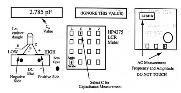
HP4275A front panel. - Remove any device from the test fixture. Press zero open to calibrate the instrument.
- Place the transistor in the text fixture as shown in the figure above. The base should be placed in the side marked low and the collector should be placed in the side marked high. Use the screws to tighten down the clamps, but do not over tighten.
- A coaxial cable can be found in back of the instrument that is connected to the DC bias input. Connect this cable to the nearest power supply (connect + to + and - to -).
- Set the power supply to the desired value of VCB. Read off the value of Cµ from Display A.
Circuit Models Used in Calculations
The HP4275A uses the following circuit models and calculations depending on the configuration of the instrument.
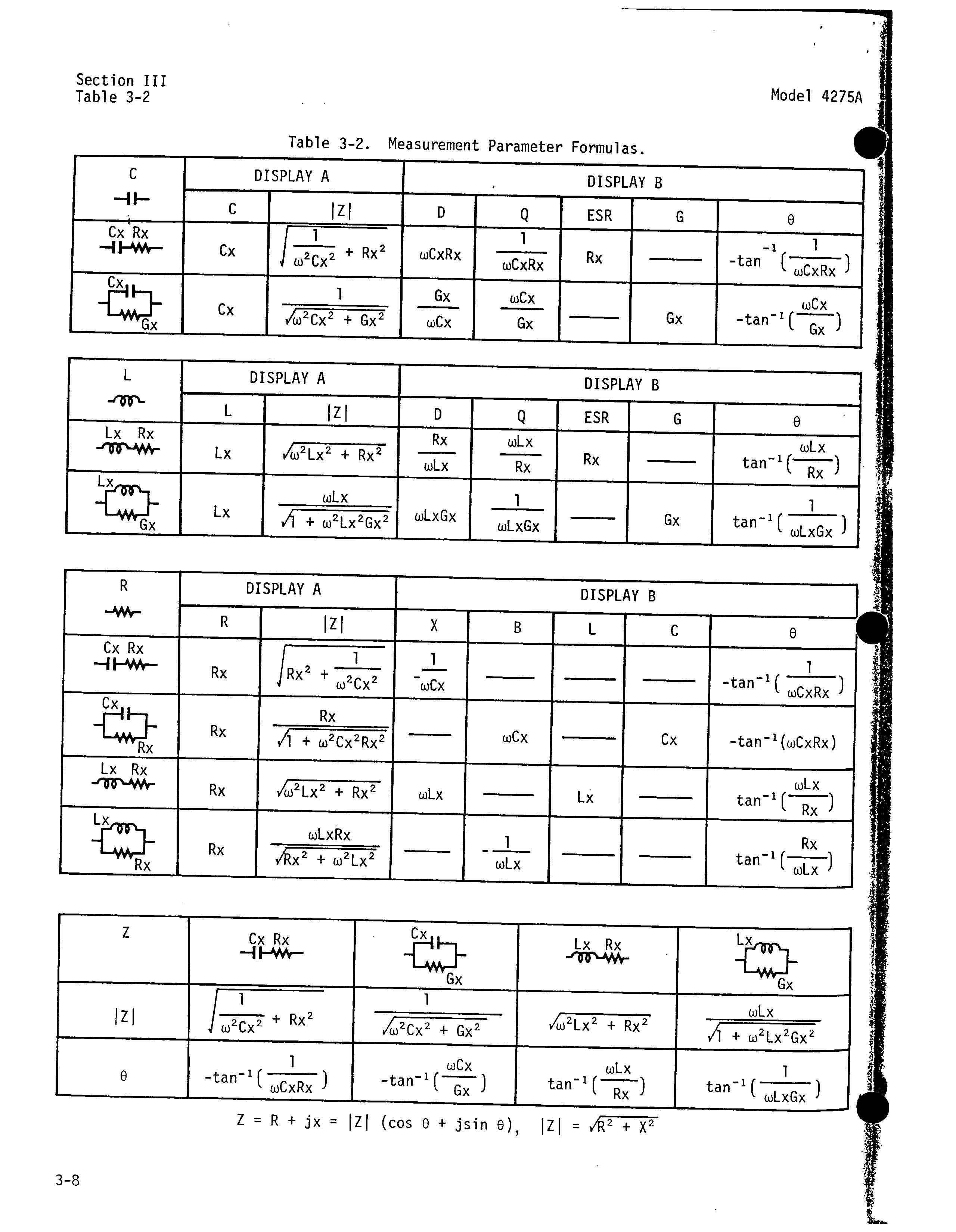
Circuit models and equations for impedance calculations.