Traction Control Simulation Vehicle Project
Team Members
- Walter Olds
Project Overview
The purpose of our project was to simulate a speed modulating traction control system with a concept similar to that of racing traction control systems, which control vehicle stability through braking and engine power delivery management. Our vehicle was constructed using two independently controlled servos as motors for the drive wheels, along with an acoustic distance sensor to measure the vehicle’s relative position. Running the car on equal or unequal friction surfaces with the traction control system activated demonstrates our ability to control the wheel traction by steering the vehicle along a straight path relative to its start position.
Project Approach
When approaching this project, we knew that the most important aspect was servo control, so we began with modifying and characterizing each of our servos. Next, we characterized the acoustic distance sensor and began to construct the vehicle, mounting the servos, sensor, front wheel, and the proto-board along with the on board circuit. After some debugging with various hardware issues encountered with the car outlined above, we first mapped out a general guide/traction control algorithm that would fulfill the needs and capabilities of our project vehicle. We then began to write the algorithm and after extensive debugging, testing, and surface selection, we were satisfied with the results we were able to obtain within the limitations, so we proceeded to implement the push button interrupt and guide/traction control enabling toggle switch.
Encountered Issues
Limited servo control with angular modulation was a big problem. For the purposes of our project, the different servo speeds achieved using this method did not provide noticeable variation in servo speed when turning the drive wheels. Therefore, we re-characterized the servos based on pulse width modulation, effectively alternating the cycles in which high pulses were transmitted, providing much more servo speed control. This led us to discover that we had to reverse the polarity of one of the servo motors to drive it in reverse as it was mounted opposite the servo on the other side of the vehicle.
We also encountered interference from running signal wires through ribbon cable over long distances. We resolved this issue by attaching every other wire in the ribbon cable to a common system ground.
Unresolved Issues
Even though we acquired precise control of the servo speed, the traction control aspect of our project would have been more visually dramatic if the servos had a greater speed range. This would have allowed us to show the effect of slowing down both wheels to the maximum speed of the slowest wheel upon start up of the car and then increasing the speed of both wheels as the vehicle gained momentum.
Non linearity of the distance sensor throughout the sensing range limited the ability of our vehicle to correct its path to within a distance of about 6 centimeters. Therefore, we had to be careful when placing the vehicle for start up so that it would not become too far off course too suddenly, before our algorithm could correct it.
Pictures
-
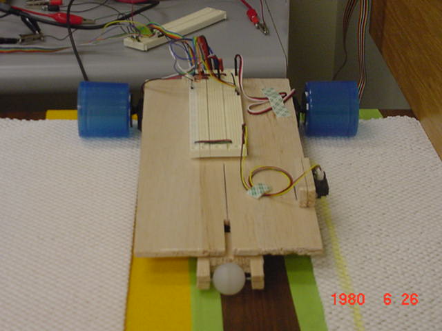
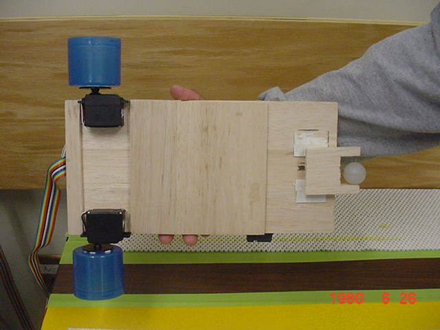
Vehicle Side View
-
Vehicle Front View
-
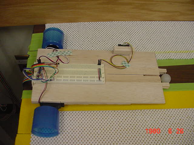
Vehicle Bottom View
-
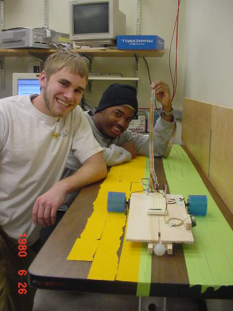
The joy of finishing a project previously unattempted!
Movie Clips
- Vehicle on equal traction surfaces without compensation.
- Vehicle on equal traction surfaces, guided by our algorithm.
- Vehicle on two unequal traction surfaces without compensation.
- Vehicle on two unequal traction surfaces, guided by our algorithm.
- Vehicle on two additional unequal traction surfaces without compensation.
- Vehicle on two additional unequal traction surfaces, guided by our algorithm.
Links