for EECS 373 - Fall '05
Group Members: Gunjan Patel and Stephen Leverett
|
|
|
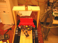
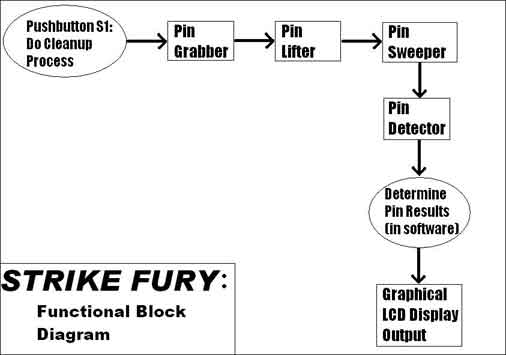
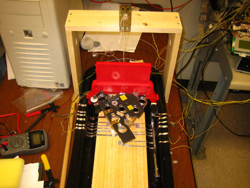
Our project automates a control system for a small toy bowling alley. These controls are primarily involved in the “clean-up” process after a ball is rolled. Our idea was to automate as much of this process as possible, including grabbing the pins, raising the pins into the air, sweeping any knocked over pins and the ball, and detecting which pins remain after the turn. Additionally, we used a graphical LCD to show which pins remained after each roll. Our goal was to automate one frame of bowling such that the user would only have to roll the ball and press a pushbutton while our software and hardware took care of cleaning up and tracking which pins remained.
The most important control concept for our project involved the speed of our motor and servos. The DC motor had to be timed to raise and lower the pin apparatus properly, but not too quickly to the point that it might jerk and knock out a pin. Also, the servo that picked up the pins had to run briskly in order to pick up the pins without knocking them over.
Pin lifter: Driven by a DC motor, electrically controlled by an H-bridge to go forwards and backwards. The motor was mounted to a wooden apparatus built over the bowling alley that pulled the pinsetter off the floor during the clean-up process.
Pin sweeper: Also driven by a servo. This component was attached next to the gutter inside the bowling alley.
Pin detector: To detect the pins, aluminum tape was laid onto the floor of the bowling alley and washers were placed onto the bottom of the pins, which would complete the electrical connection when present.
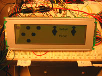
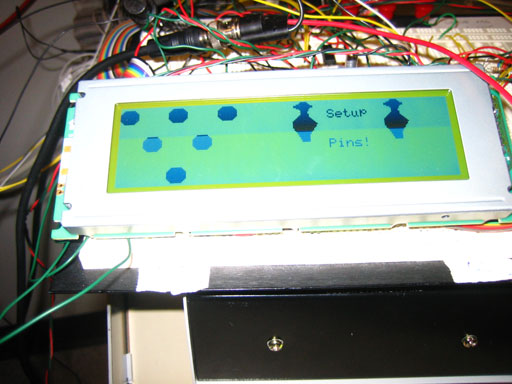
Graphical LCD Display: Instructs the player on what action to take, i.e. setup the pins, roll the ball. Also shows which pins are standing and displays graphics when the player achieves a spare or strike.
For controlling the servos, we decided to construct hardware timers using counters and comparators to generate the pulse width. This helped to free our software timers for other needs. The input value for the pulse was given by the data assigned to the address of the servo.
On/Off and Control outputs for the H-bridge were implemented in hardware. The control signal would set values on the H-bridge to make the DC motor go forwards and backwards depending on the data written to the address of our H-bridge hardware. Again, the DC motor attached to the H-bridge was used to pick up and lower the pins.
The interface to the graphical LCD controller was made in our hardware. The hardware primarily involved creating timing signals to the LCD controller’s bus using wait states for proper setup and hold times.
Since many of our test points were occupied by the LCD and servos, and we wanted to use test points for pin detection as well, we copied and modified hardware for the 7-segment display buffers in order to interface with the test points. Specifically, six of these test points used input buffers so we could check the status of circuits to six our six pins. These pin sensors followed a simple scheme: if the test point was high, then a pin is present, otherwise the pin was knocked down.
To turn the DC motor on and off, we used a software timer. Since we were unsure of which DC motor we’d use at first (i.e. a slow motor that’s very strong and has high torque or a smaller motor that’s fast but weak), we wanted maximum versatility and ease in changing how long the motor was on. Since the software timer allows us to easily select range and resolution by changing a few parameters, we decided to dedicate one of our timers to this rather than using a clumsier hardware approach.
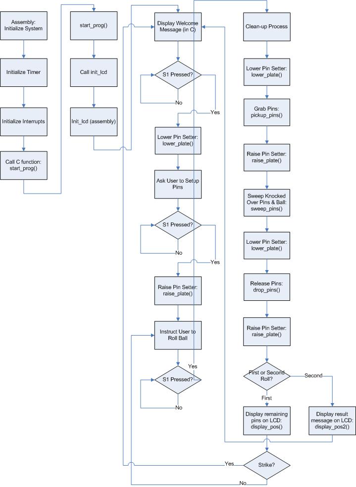
The user must press S1 to start the cleanup process. Our software waits for this by using a while() loop in our C code. We decided to do this instead of an interrupt because nothing else is going on in the game at this time; we are only waiting for the user to bowl and press S1.
Our use of assembly code was limited to initialization and interrupt routines. Initialization involved setting up timers and interrupts along with initializing the LCD display using the prescribed routine from the LCD documentation. The vast majority of our code was implemented in C. After the initialization in assembly code is finished, we branch to our C code. The C code writes a welcome message for the LCD, tells the user to roll a ball, and performs the “clean-up” process in sequence: lowers the pin setter, grabs the pins, lifts the pins, sweeps knocked over pins, lowers the pins, releases the pins, and raises the pin setter.
Overall, our design worked the way it was expected. We were able to effectively automate the bowling process and display results on our LCD. But our design wasn’t without a few problems. For one, about one out of every five times, the pin grabber wouldn’t release a pin so that it was standing up straight. Improving this would require other mechanical solutions such as using a metal gripper that wraps around the pin neck. The biggest problem we encountered was reliably detecting leftover pins. Either extra pressure was needed by physically pressing them down onto the aluminum strips or soaking the washers attached to the bottom of the pins in water to increase conductivity. Obviously neither of these solutions were ideal. We could have also tried to use other kinds of washers and tape to see if we could make a better connection or use pushbuttons that physically close the connection when they are pressed. Early on, we also considered using distance or light sensors to detect the pins, but this seemed overboard. Our solution with the aluminum tape and washers was fine for a prototype, but is definitely an area that could be improved upon if we were to make another version.
Our impression of our project in the end was that it posed many more mechanical problems than we had anticipated. The most formidable problem was grabbing the pins. Our first idea was to pinch the pins against the side of the pin setter. But the pins very often did not stand up straight upon release. Our second idea was to use electromagnets to pick of the pins. Unfortunately, the electromagnets drew too much current to make this solution feasible. The only way to lower the current was to wrap the coils bigger, which would’ve been pushing weight constraints, or buy industrial manufactured electromagnets, which was an unnecessary expense.
It is definitely possible to implement our idea with our components. Obviously our small servos wouldn’t be large enough for a real bowling alley with large, heavy pins and balls, but for a miniature toy set, the servos and motor were adequate for performing the pin clean-up process.
Our design was not in need of any additional processing power. If we had done fancier animated graphics, we could have possibly run into a constraint here, but for controlling the bowling alley, the MPC823 was amply powerful.
If we were to do this project again, there would be a few things we’d do differently. For one, we’d find a more reliable way of detecting pins. Perhaps six light sensors mounted on top of the pin setter would’ve worked. We’d also try to implement a detector to determine when the user had rolled to start the clean-up process automatically rather than requiring the user to press S1. One idea we had for this was to put a small microphone at the end of the bowling alley to detect sound and vibrations that would send an interrupt to start the clean-up process, but as we ran out of time at the end of the project, this feature was never implemented.
The Bowling Alley | |
 |
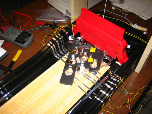 |
The Protoboard | 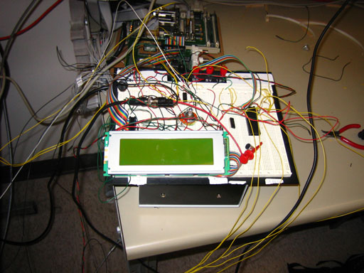 |
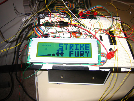 |
The LCD | 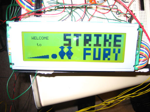 |
 |
H-Bridge Documentation: Texas Instruments SN754410
Graphical LCD Documentation: Optrex DMF 5005N