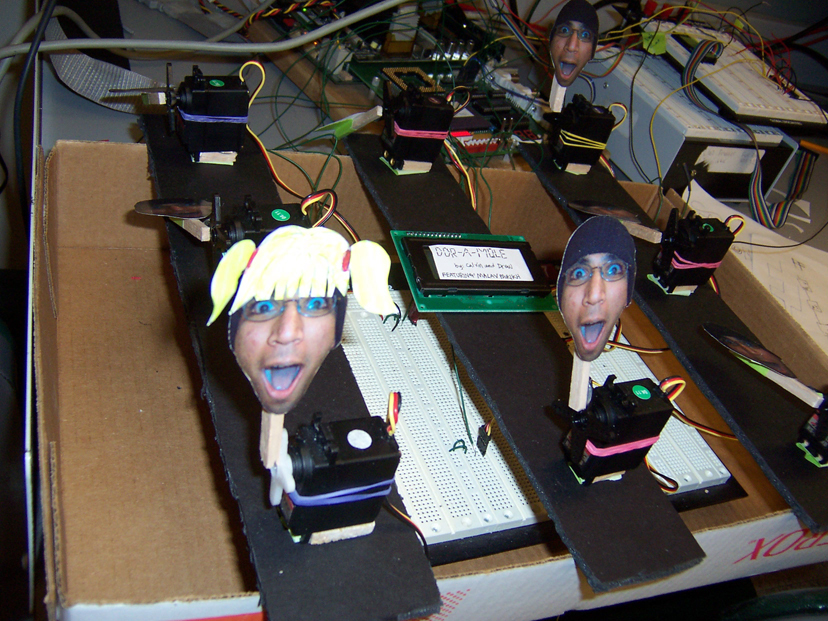
Project Title: DDR-A-Mole
Members: Drew Mokris and Calvin Cheung
Introduction:
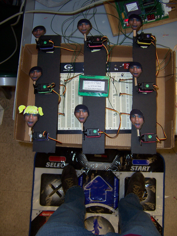
We set out with the goal of creating a Whack-A-Mole game with a twist.
Whack-A-mole, for the unfamiliar, is a game in which puppet "moles" pop
out of holes in a table like surface, and the player (usually a child),
must "whack" each mole with a padded mallet before it retreats back into
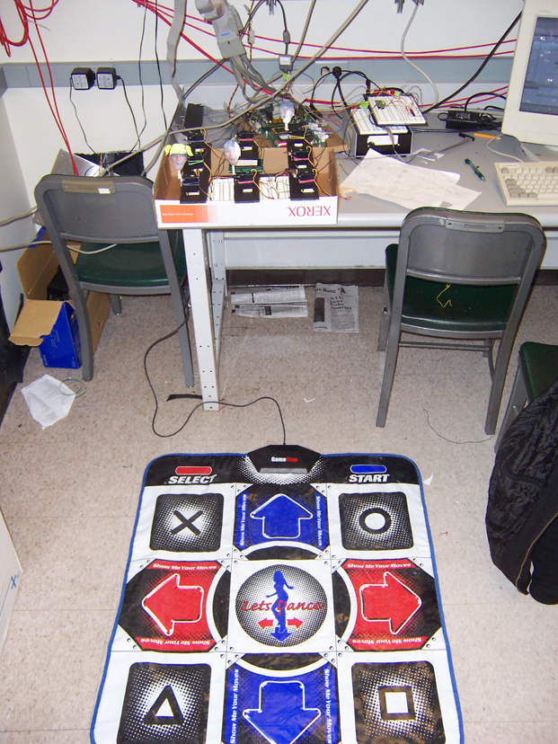
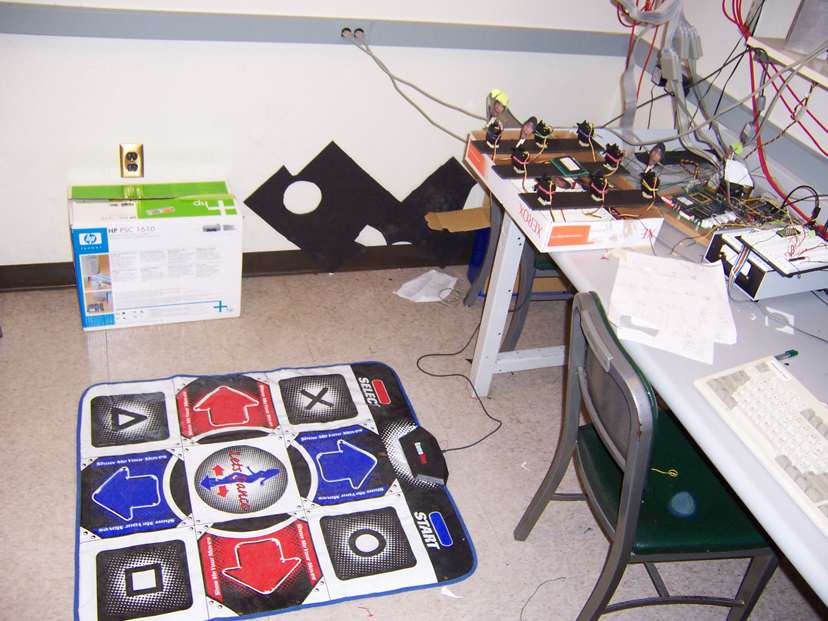
its hole. The difference with our version is that the player would not
be using a mallet, but rather a Dance Dance Revolution (DDR) pad. The
pad, which is a playstation controller, has eight steppable buttons, and
the game is played by pressing on a button to "whack" a corresponding
mole when it pops up. The other difference with our version was that the
moles were not moles, but Malavs.
High-Level Design:
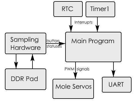
The design, while not completely interrupt driven, would not work without several
crucial interrupts. The duration of the game is timed by one-second interrupts triggered
by the MPC823's Real-Time Clock (RTC). Moles are only raised for a short duration of time
as determined by 1 millisecond interrupts triggered by the internal timer.
The controller is poled regularly, and each time it causes its own interrupt,
at which time the button statuses are copied into memory, where the main
program can access them. The main program employs a rudimentary random-number-generator
to choose a new mole to assert whenever it needs to, and sends Pulse-Width
Modulated (PWM) signals to the eight servos acting as moles. It also repeatedly
updated the UART window to display the current score and seconds left
in the game.
Member Task Distribution:
Drew: Created hardware to interface to DDR pad, and wrote corresponding interrupt handlers, created
PWM hardware for servos, and worked on general program design and debugging.
Calvin: Wrote main program loop, RTC and Timer Interrupts,
memory-mapped the servos, UART updating software, and worked on
general design and debugging.
Hardware Design:
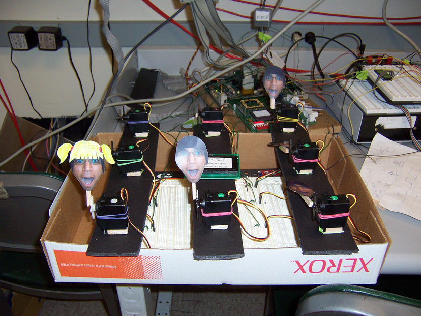
Servos:
Our servos only needed to be able to turn to two states, "up" or "down".
This simplified our hardware, in that we only needed to produce two
different PWM signals (each with a period of twenty milliseconds). The
"up" state had a high-signal duration of 2 milliseconds, and the "down"
state had a high-signal duration of 1 millisecond every period. We created
these pulse signals but repeatedly dividing the system clock (which
we measured to be 20MHz, not 24 MHz). We used a set of 8 flip-flops
to store the up/down states of each servo, and then used these bits
to select which PWM signal to send to the corresponding test-point.
These flip-flops were then mapped to a write-only portion of memory
(namely, at address 0x02500000), so that the main program loop could
write a byte to change the moles statuses.
Timers:
We used one of the MPC823's internal timers to throw interrupts and increment local variables
in the main program. We initiated the timers to have the necessary prescaler settings to trigger
an interrupt every 1 ms.
Real-Time Clock:
We also set the MPC823's RTC to trigger its own interrupt every 1 second. This was used to increment
a local counter variable, which stopped the game when it reached its 20-second limit. It was also used
to selectively update the UART display to reflect the latest time and score.
UART:
We used the drivers given to us in adsinit.o to call ser_getchar() and ser_putchar() and display information
on the UART hyperterminal window as the game was played. Every second (as timed by the RTC), we cleared the buffer
by putting a series a backspace characters, and then printed the newest score and game time.
DDR-Pad:Easily the most time-consuming part of this project. We had very little
documentation on how to interface to a playstation controller, and this made our task very difficult.
In the end, the hardware did not need to be very complicated.
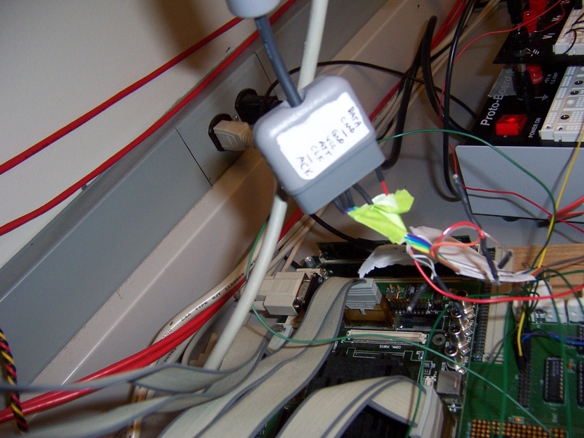
We needed to work with only five pins on the playstation controller: DATA, GND, VCC, ATT, and CLK.
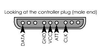
The ATT ("attention") line was pulled low about every 0. 8 milliseconds
(for about a 1. 2 KHz sampling rate). This signal is used to tell the controller
that we are paying attention to it. After ATT goes low, we wait 28 clock
cycles on our CLK line (which runs at 156 KHz. We determined this value
by experimenting, and observing the interactions between the controller
and an actual playstation). After waiting, the controller then starts
driving its serial DATA line. It tells us the active-low statuses of each
of its buttons in a specific order, and we are able to latch in these
values and read them on each sampling.
Software Design
Use of Timers and Interrupts
The Real-Time Clock and a timer was used to throw interrupts. The Real-Time Clock threw interrupts every second,
while the timer threw an interrupt every 50 milliseconds. Both were used as counters to variables set in memory,
that were accessed in C through the use of pointers.
Every time the Real-Time Clock threw an interrupt, a game timer value was incremented in memory. A conditional
statement in the main game loop checked to see if a previously stored value of the game timer matched the current
value. The values not matching indicates that a whole second has passed. When a second passed, we updated the
game time and score on the terminal.
The timer interrupt was used in a similar fashion. The timer interrupt incremented 3 values that were
stored in memory every time an interrupt occurred. These values were used to determine how long a single
mole had been up. If a mole was up for a set period of time, the corresponding value in memory was zeroed
out so that the next mole can have a fresh timer count.
Distribution of C and Assembly
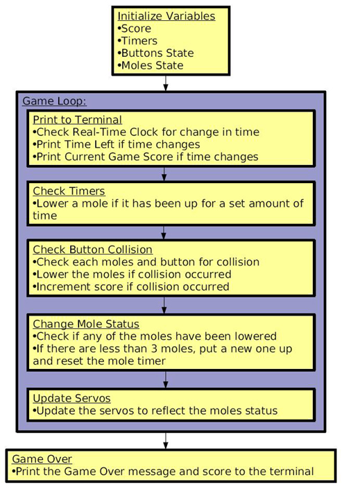
The software begins with the assembly code initializing all of the timer and Real-Time Clock registers.
After doing so, the C function terminal is called, which contains the main game loop. In terminal,
assembly functions are called that return the memory addresses of the variables used to store the mole
timers and game time. The C function terminal then continues to run as illustrated in the flow chart.
The program continues to run until interrupts are thrown from either the timer or Real Time Clock. The
interrupt handlers increment the necessary variables in assembly, and then continue with the execution of
terminal. After terminal has run to completion, it program returns to the assembly code and stops at done.
Program Flowchart
Results and Conclusions
We had a host of problems and difficulties, but most of them came from
our limited knowledge of the playstation controller. Our first understanding
of the specifications we could find indicated that playstation controllers
required us to send them a pair of byte patterns on a CMD line immediately
after pulling ATT low, and that the pad would not respond until
our hardware did so. Some of our first readings of the controller's
DATA line on the oscilliscope showed that it was obviously sending
us its button statuses, so we thought our serial-out shifters were
working correctly. We later realized that this part of our hardware
was flawed (and causing other problems), and upon further investigation,
the controller didn't care if the CMD line was even plugged in!
This would have saved us a lot of time if we had discovered it earlier
(although, strangely, no other DDR pad or playstation controller
that we attempted to characterize would respond the same way our
original pad would, so we haven't been able to generalize this behavior
to all playstation controllers. The third-party controller we were
using may have just been lazily made).
Another notable problem with the playstation controller was that its DATA line output was hardly able to
push the 0 to 5 volt settings we needed. We could see that it was responding to button pushes on the
oscilloscope, but its signals barely reached over 1 volt, and there were also visible perturbations
from the CLK line. Matt Smith suggested buffering our outgoing signals by running them twice through
inverters. We tried this with little luck, but we found that running the incoming DATA signal through
the inverters DID boost its level to the necessary voltages. Although we still aren't sure why the
controller had such trouble (again, it may have just been poorly made), this was our solution.
We also wasted at least two valuable days with a seemingly bad lab station which was refusing
to send our ATT signal properly. We assumed it was the fault of our hardware, and it plagued us
until we realized that simply switching to another station solved the problem. We never diagnosed
the exact problem, but the oscilloscope showed a lot of noise on every signal we gave it at that station
(for all we knew, it could also have been an oscilloscope problem, since that's what we used to monitor
all of our signals).
We initially planned to include an LCD display in the center of
the eight moles, upon which we wanted to display the current score
and time, but because of the DDR pad, we completely ran out of time
to figure out how to interface to the character display LCD, so
the UART became our alternative. Our final design would randomly
stop with the message "Software Emulation Exception", which we believe
to be the fault of writing characters to the UART too quickly (but
unfortunately, this exception was NEVER repeatable, and therefore,
impossible to debug). Our very original proposal also included a
speaker, so that there was some indication to the player that they
had hit the mole, but this was scrapped after reviewing our proposal
with Matt Smith. In the end, the only feedback that the player recieved
upon hitting a mole (other than a score increase on the screen to
their right) was that the mole immediately went down.
Our biggest software bug was in not properly checking button statuses
before asserting a NEW mole. This caused our (poor) random number
generator to attempt to put up the same mole many times in a spot
that was already being "whacked" (which caused the scores to inflate
unrealistically). This problem also took very long to find.
If given we could repeat the project, we would hopefully have more
accurately characterized the DDR pad, so that we hadn't wasted any
time on portions of the design that were unnecessary. If we knew
what we know now, we could have completed the pad interface in an
eighth of the time, giving us much more time to have incorporated
the LCD.
Despite the limitations and time-restrictions, we achieved what we wanted to: a playable game with
effective scoring in which pressing the buttons on a game controller had immediate effects. We enjoyed having complete
creative design control and freedom, and it was very fun to realize that the concepts that we had
touched-upon in class were being employed in many places, even a video-game controller.
References:
|