| links | |
|
[home] [high level design] [task distribution] [hardware design] [software design] [design results] [conclusions] [media] [links] |
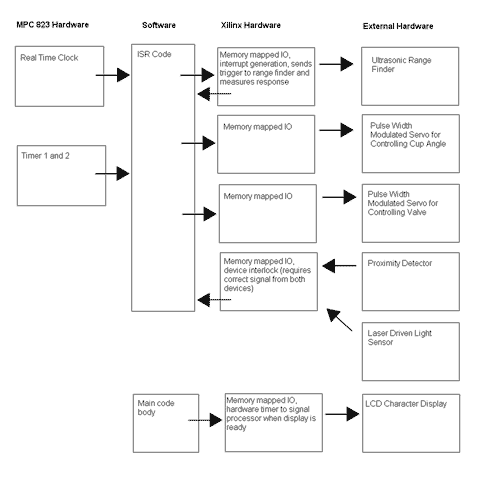
The Automated Beverage DispenserTeam Members:Michael Everhart David Castellani High Level Design: Control and Measurement Concepts: The general premise of the design required a number of interconnected sensors actively providing status data to our program. A pair of sensors rest in the area of the swivel mounted cup holder to detect the existence of a cup. A photo detector acting as a general safety mechanism is implemented strictly through hardware and prevents the beginning of operation until broken. A second close proximity distance sensor rests at the base of the holder and detects the proximity of an object in software. The pair acts in conjunction to prevent any accidental spilling. The heart of our measurement systems however is a sonar emitter/detector (ranger) used to detect the water level present in the cup as the device begins to pour. The sonar wave is emitted and received by the same device mounted just outside of the cup in an attempt to prevent any sound wave distortion. The signals provided from the sonar device are used to determine the water of the level and are used to determine the cup position. When the cup is empty and present the device moves the cup into its initial pouring position. The data read from the sonar range finder is used to control the cup level and water flow. When the water in the cup reaches a certain level, the position is changed. If the cup is appropriately full, the water stops flowing. Functional Subcomponents: 1) Display: Take information from the processor provided by program to display current status of the machine (i.e. filling, waiting, etc.) 2) Sonar ranger: Input from the processor emits a restricted frequency signal from the ranger and starts a hardware counter. When the signal is received the counter is stopped and number appearing in the counter is used to determine distance traveled by the sound wave. 3) Narrow proximity detector: Emits a restricted frequency light wave that reflects off of any object within range to provide a digital response to the processor alerting it to the proximity of an item. Used in conjunction with the photo detector as a “begin” signal as a safety interlock. 4) Photo detector: Detects a beam of light from a laser pen and provides an output voltage depending on the amount of light being shone on it. Once the laser is broken the output analog voltage output is filtered through hardware to a digital “0” that alerts the processor that it has been broken. 5) Valve control servo: Uses a pulse width modulated signal from the processor defining a given position to spin to. Once this position is reached the water valve has been pulled and water begins to flow. The device must be constantly pulsed so that the valve is prevented from releasing itself. 6) Cam control servo: Uses a pulse width modulated signal from the processor defining a given position. A cam attached to the servo moves the cup holder into a specified position and is repeatedly pulsed in order to keep the cam and arm in the desired position. 7) Software: All of the code controlling our design except for the display was implemented inside of our interrupt service routine. Inside the ISR there are functional blocks for each of the interrupt generating devices, including the real time clock, the MPC823 timers, the sonic ranger, and the display delay controller. 8) Timers: The MPC823 timers were used to generate the pulse width modulated signals required to control the two servos. The exact PWM signal varried depending on the position of the cup platform and the valve. 9) Real time clock: The real time clock was used to check the liquid level every second. The slow liquid level update frequency required the use of a lower flow rate of beverage into the cup, to avoid overflows. Functional Block Diagram Click for a larger image.
|
