Laser Display SystemFinal Report |
Nathan Gallaher
Steven Klimczak
Patrick Macnamara
![]()
In our final project, we set out to build a raster display using a laser. We hoped to achieve a 20 pixels by 20 pixels at a modest 5 frames per second. We wanted to demonstrate the laser display system in two ways. First, it would be able to display scrolling text input through a simple command-line interface in HyperTerminal. Second, it would be able to display a "dimmed" output based on the digital value provided by the ADC. Thus, the system would display a number of red dots determined by the value from the ADC. We also added two short sprite-based animations.
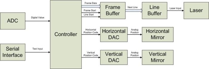
The horizontal and vertical scans were provided by two speakers that modulated the angle of two mirrors. The position of each mirror could then be controlled by the microprocessor, which would write digital codes to two DACs. The two DACs provided a voltage to the speakers, thus controlling the position of each mirror. In tandem with the write of the DACs, the microprocessor generated frame and line start signals, indicating the beginning of the frame and line, respectively. The frame data was stored in a buffer in hardware. The frame start signal generated by the microprocessor would cause the first line of the frame automatically to be loaded into a line buffer, which would clock out the data serially to the laser at a frequency set by a prescaler in hardware. The line start signal would cause the frame buffer to send the next line to the line buffer. Software would work by continually modifying the contents of the frame buffer.
Nathan Gallaher
The current frame was stored in a 128 byte memory on the Xilinx FPGA. Each 20 bit line was stored in the top portion of a 32-bit word.
In addition to the frame buffer, a controller was designed that selected the address of the next line and generated the signals to latch in the next line into the line buffer. When the microprocessor was attempting to read/write to a location in the frame buffer, the controller always selected the address from the address bus. Otherwise, the controller used a counter to cycle through the address of each line in the frame. The line start signal was used as the clock for the counter. In addition, a rising edge of the frame start signal cleared the counter. Morevoer, whenever a rising edge of either line start or frame start was detected, a signal was generated to latch in the selected line into the line buffer. This latch enable signal was generated by sending the frame_detect and line_detect signals through two D flip-flops clocked by the serial laser bit clock.
The line buffer was simply a 32-bit shift register that loaded in a new 32-bit line on the latch enable signal generated by the frame controller. It was set up so that the most significant bit was output first. Thus, for a 20 bit line, the 20 bits of the line must be stored in the top half of the 32-bit word.
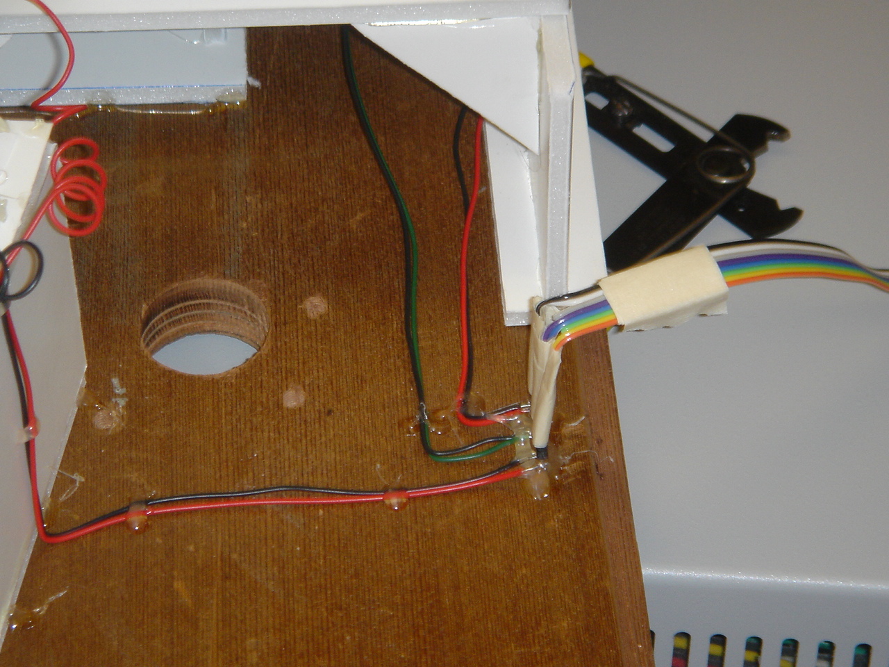
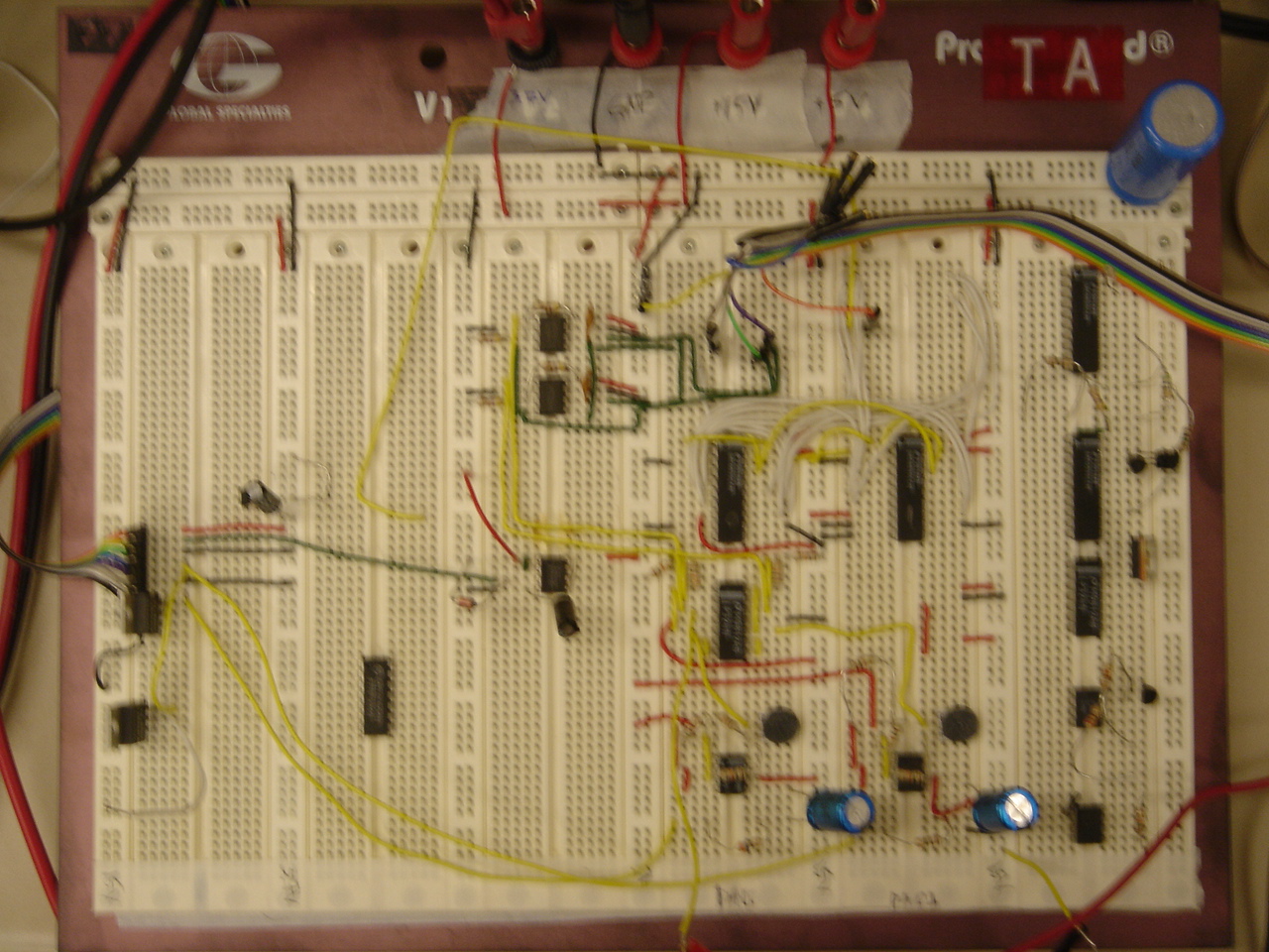
The Maxim MAX541 DACs were wired up on the breadboard and we mapped the control lines to the DACs through testpoints. The output of the DACs were connected through an amplifier, a voltage follower, and a power amplifier to the speakers. The serial data line was mapped to a testpoint, and connected to the laser through a peripheral driver.
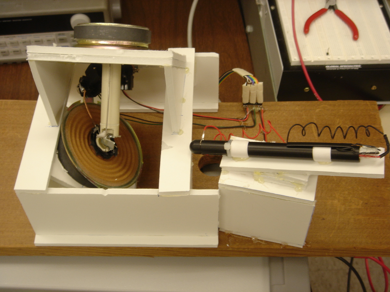
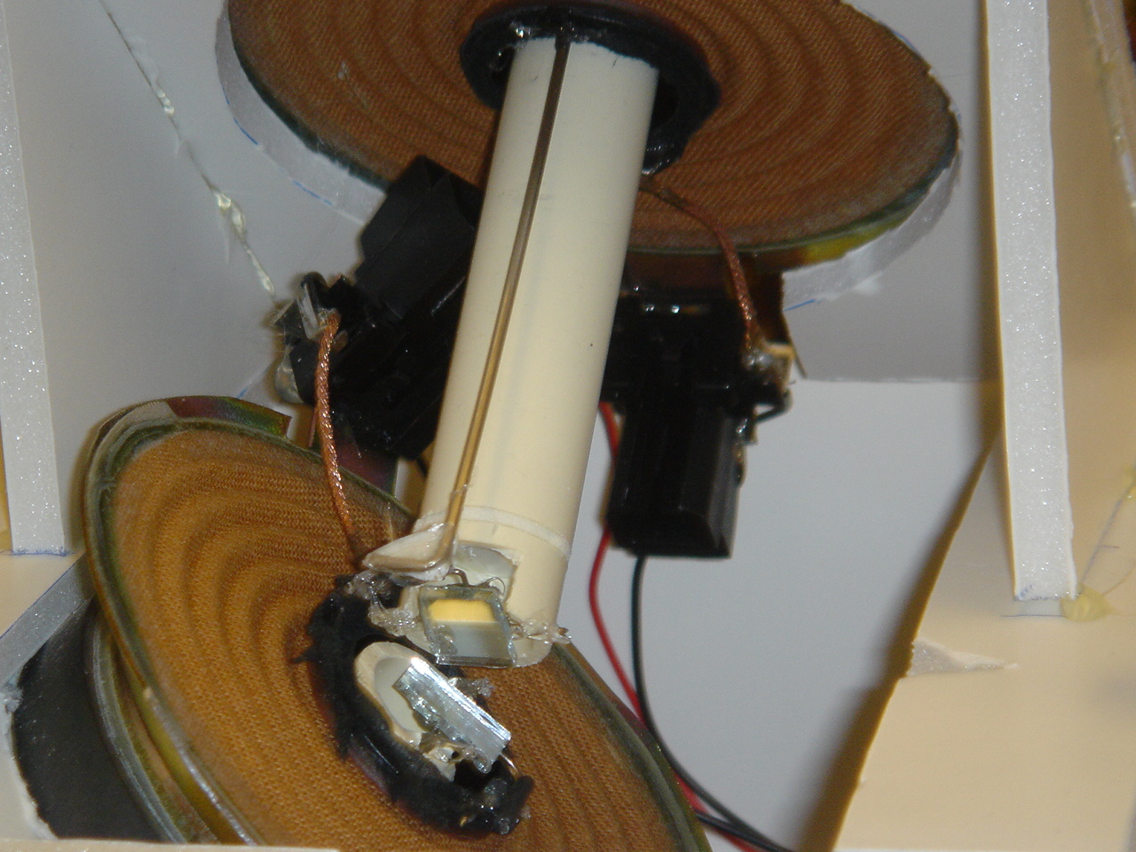
The DAC signals are used to drive a pair of speakers. These speakers have had their audio cones and domes removed and a hinged mirror connected to the driver coil. Thus, when an audio signal sent to the speaker will modulate the angular displacement of the mirror, allowing us to sweep the laser across the projection surface. Mounting two such assemblies orthogonally allows us to sweep a two dimensional space.
The laser is modulated by switching the power to it. Selecting a driver that could switch fast enough as well as source enough current was a challenge, but in the end we found that the SN75451 driver was sufficient for our needs.
The user interface is provided through the HyperTerminal UART program. The user is given the choice to display either a square with dimness relative to the voltage on the ADC, a maze with the solution shown one pixel at a time, a sprite animation of a guy in 'paradise,' or a scrolling marquee. If the user chooses the scrolling marquee, they are then prompted to input the marquee text. Valid characters are alphanumeric, space, and period. The marquee can be up to 22 characters in length. Both upper case and lower case characters are valid, but both are displayed in the upper case form. To exit from any display mode and return back to the main menu, press Enter.
It is up to the user to follow the input guidelines. At the main menu, any invalid input sends you to the scrolling marquee function. At this prompt it's garbage in, garbage out. The backspace key is implemented, so the user always has the chance to get it right.
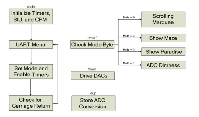
First we initialize timer1 and timer2, the System Interface Unit, and the CPM Interrupt Controller. Then we use the UART to create a text menu-based interface. The user's choices set a mode byte in memory and can create a string for the scrolling marquee. The timers are both enabled and the main part of the program continually looks for input on the UART. Moreover, nested interrupts are enabled by setting and clearing the EE bit in the MSR during the operation of timer2. This is done to ensure that the microprocessor always updates the position of the mirrors when necessary. When a Carriage Return is found, the timers are both disabled and the menu is given again.
Timer1 drives the DACs. There are two position arrays and one index apiece into these arrays. The next DAC positions are loaded and sent to the DAC registers, and the indexes are updated and saved. Timer2 fills the frame buffer depending on the mode byte in memory. The scrolling marquee code indexes the character display arrays for the displayed string characters, shifts them based on a scrollbit, and stores them to the frame buffer. The scrollbit is then incremented and the process repeats until the end of the string is reached, at which point the string pointer is reset to the beginning of the string. The maze code first fills the frame buffer with a maze, then writes the lines that the solution is found in one at a time. The paradise code simply writes the five key frames of the paradise animation one after another. And the ADC code starts a new conversion on the ADC, loads the result of the previous conversion, indexes a 'dimness' array with the value, rotates the dimness word in a semi-random way, and finally fills the frame buffer with these words. The dimness array is filled with words of increasing numbers of high bits. Finally, IRQ1 reads the conversion byte from the ADC and stores it in memory for timer2's eventual use.
The demo software is written in assembly. Test code was written in both assembly and C. Figuring out how to handle both timer1 and timer2 interrupts correctly was a pain. Debugging the code was also difficult because different problems occured on different workstations. Also, the best way to debug the output was to take a look at the laser display output to see exactly where things were going wrong, but this requires a working laser display to debug on. Much of the final debugging of the timer2 code was held off till the final days of work.
We had difficulty controlling the position of the speakers with the 8-bit National Semiconductor DAC0830 DACs. First, we could not get the output of the 8-bit DACs to be monotonic. Second, the resolution was too poor for us to control the mirror position well enough. Therefore, it became very difficult to place pixels where we wanted. We overcame this problem when we switched to the 16-bit Maxim MAX541 DACs.
Moreover, we had to compromise the frame rate and frame resolution because of limitations of the speakers and the Motorola MPC823 microprocessor. In addition, we had originally planned on using a rotating mirror assembly to generate a horizontal and vertical scan. We abandoned this approach for several reasons. First, in this setup, we would have needed to control the speed of the vertical and horizontal motors rather than the position of each mirror. Thus, we would have run into problems getting the two motors to be synchronized. Second, to generate the vertical scan, we had planned to physically rotate the laser. In order for this to work, the laser would only be able to output data for a small portion of the rotation. Thus, it would have been difficult getting the horizontal mirror to rotate at the necessary speed.
Thus, were were able to implement a one-color laser display system with a small resolution and modest frame rate. With our components, it would not have been possible to create a higher resolution display. We likely would have needed a faster processor and a way to modulate the position of the mirrors fast enough.
Given what we know now, we would not have spent any time trying to build the laser display using rotating mirrors. In addition, we would have written more of the code in C. This would have made it much simpler to add features.
| Laser "Rig" | Horizontal and Vertical Mirrors | |
 |
 |
|
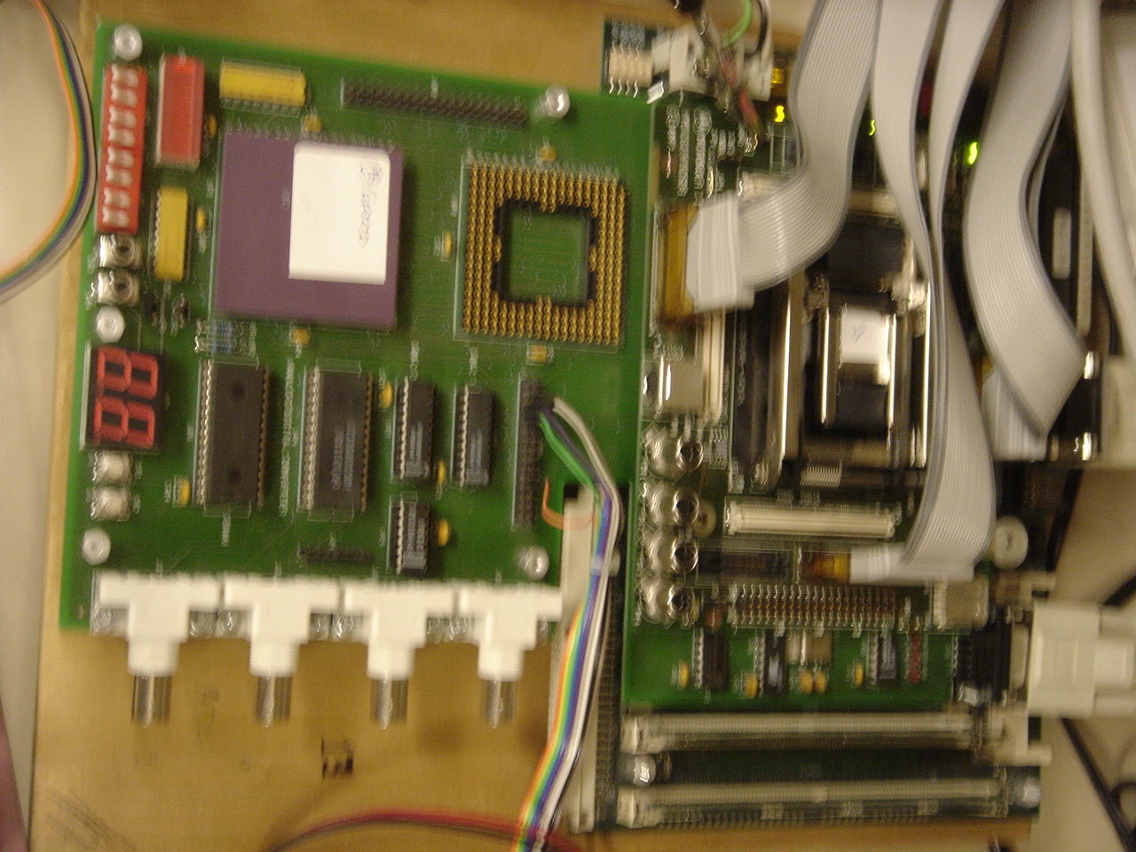
| Connection to Breadboard | Breadboard Circuit | |
 |
 |
|
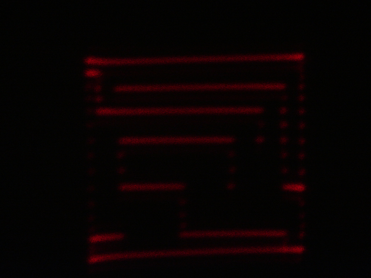
| Connection to Lab Board Test Points | Maze Screen Shot | |
 |
 |
|
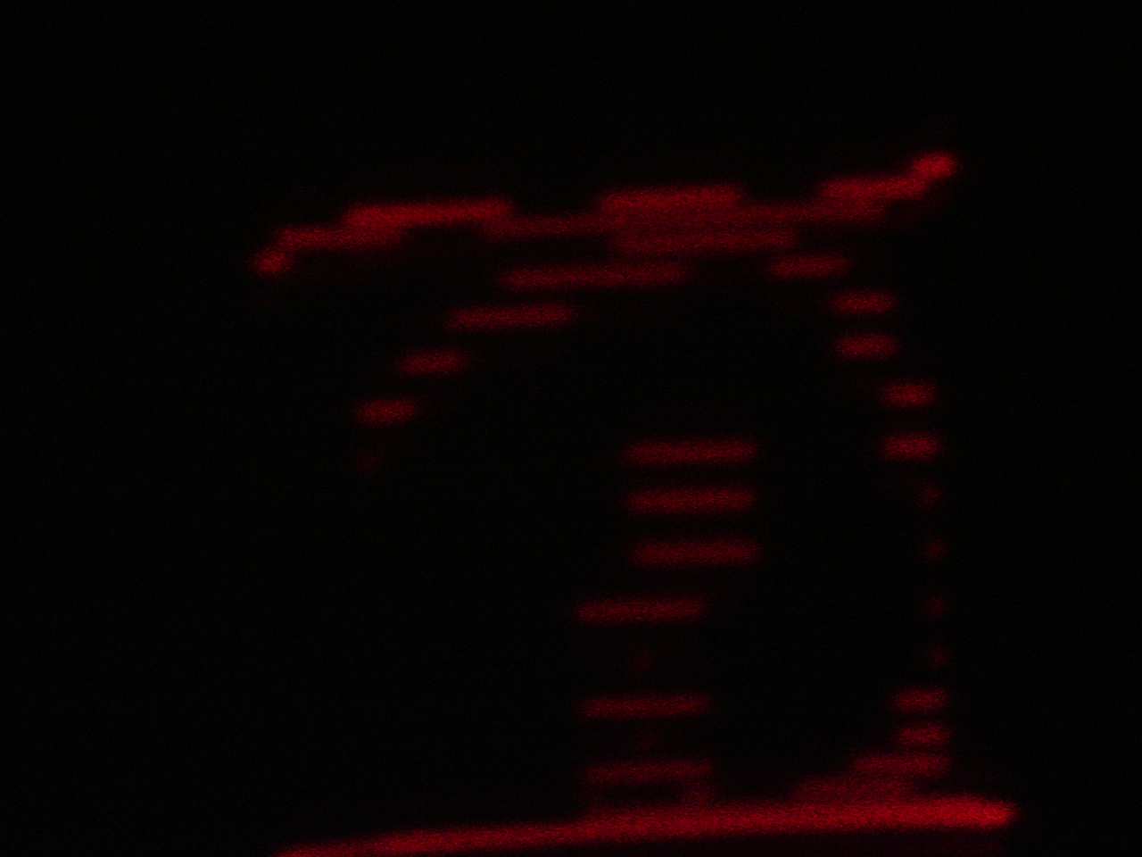
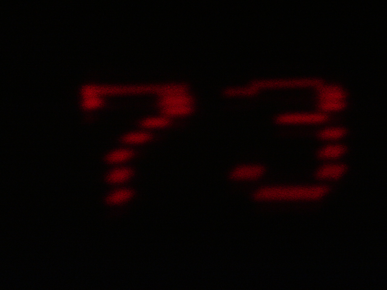
| Paradise Screen Shot | Scrolling Text Screen Shot ("73" is part of "EECS373") |
|
 |
 |
|
» Maxim MAX541 16-bit DAC
» National Semiconductor LM324 Amplifier
» National Semiconductor LM386 Amplifier
» Texas Instruments SN75451B Peripheral Driver