Timer Design - we constructed various timers to suit the needs of
our design by using Xilinx hardware. For example, we needed to construct
timers in order to generate the latch and pulse signals for the NES-8
controller as well as the PWM signal for the servos. We found this to
be useful in creating sufficient timers without wasting our valuable
processor timers. This can be done by using a combination of 2 counters
followed by a comparator. Depending on the purpose of your timer, you might
consider using either a less than or an equal comparator. For the design of
our servo, we found the less than comparator to be the most efficient in
achieving our goals.
Servos - We generated Xilinix hardware to allow the NES-8
controller communicate with the servos. After the signal from the controller
is generated from the shift register (click here
for more information), we use the select signal to cause the servos to
rotate, closing the claw. The reverse effect is automatically caused through
software.
NES Controller - The NES controller is an essential component of
the core of our design (alongside of the MPC-823). The signals generated
from its data line is used to move all components of the machine. The
UP-DOWN-LEFT-RIGHT pad is used to move the main construct. The A and B
buttons are used to raise and lower the claw. Select is used to close the
claw. The start button is used to pause the game and freeze the LCD screen
(while printing a "pause" display).
LCD - The LCD was bus interfaced with the MPC
823's main data bus by way of memory mapping it to a specific address. This
same technique was used in virtually every lab throughout the term. We had
to map two unique addresses for the LCD because of the number of control
signals the LCD requires, specifically, the RS signal could be either high
or low, so two addresses were required. The basic idea for the LCD hardware
was a memory decoder unit, a several cycle delay, LCD control signal
generation and a TA_BAR signal generator. The LCD documentation was very
specific with the minimum time allowed for the control signals.
Sensors - Our initial design had a sensor system to locate and
retrieve an object placed randomly on the grid. However, with the time
constraints we faced, we were not able to integrate that particular idea
into our design. We had originally planned on using some type of light
sensor and using light emitted from the object, locate the target.
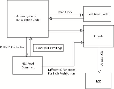
Our software consists of an assembly and a C program. The
software design was mainly initialization code done in assembly and C code
that ran the LCD screen. Assembly was used to initialize the system clock
to 10 MHz, timer 1 to send a 60 Hz irq signal, interrupt setup, read the NES
controller, setup and read the real time clock and call C code that
controlled the LCD display. The overall assembly software design was very
similar to most of the other labs that were done in class, but obviously
there were more parts to keep track of. Also, all of the interrupt ISR were
coded in assembly.
C code was used to control all the LCD functionality. We
were able to use C to control the LCD because the LCD was memory mapped, so
a simple pointer was set to the memory address of the LCD controller.
Whenever we needed to write to the LCD, we just had to dereference the
pointer and change its value. The basic flow of the LCD controller code was
as follows: each game would clear the display, reset the 1 minute timer and
give a count down to the start of the next game. Because we could only write
to the LCD, we had to use several busy wait functions to buy time between
the LCD writes. If there had been more time for the project, we would have
implemented the LCD read hardware and used the busy flag to determine when
the display was ready for the next write.
One system timer was used to poll the NES controller at
around 60Hz. Timer 1 was setup to cause an interrupt every 1/5* a second
that would trigger the NES read command from software which would transfer
control a specific C function depending on the button combination being
pressed.
Basic High Level Flow Chart of Software