Servos
 Servos
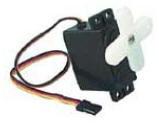
were used to control the opening and closing of the claws. As you can see on the
picture to the left, a servo is a simple motor that has 3 wires attached to it.
The red and black lines are power and ground, respectively. These are easy
enough to understand. The yellow line, the control line, is slightly more
complicated. The servo rotates according to the signal that is sent to it via
the yellow line. This signal is a pulse width modulated signal, which we will
call PWM. The PWM signal is in general sent every 20 ms. The period should not
fall below this limit or the servo risks not being able to read the PWM signal.
Servos
were used to control the opening and closing of the claws. As you can see on the
picture to the left, a servo is a simple motor that has 3 wires attached to it.
The red and black lines are power and ground, respectively. These are easy
enough to understand. The yellow line, the control line, is slightly more
complicated. The servo rotates according to the signal that is sent to it via
the yellow line. This signal is a pulse width modulated signal, which we will
call PWM. The PWM signal is in general sent every 20 ms. The period should not
fall below this limit or the servo risks not being able to read the PWM signal.
The element that controls the position of servo is the ratio of the high
level part of the PWM signal to the low level part. In other words, the duty
cycle. A graphical representation of the duty cycle is shown to the right
(reference can be found in references). In our
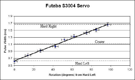
design, we used the Futaba S3003 motors. The servo functions according to the
pulse widths shown below. A 0.6 ms PW forces the servo to move to the far left.
A 1.7 ms PW forces the motor to the right.
Back to main