EECS 373 Fall 2005
Final Project
Servo Control
Members
Xuetao
LI
Introduction
The
project is to use two Photo resistors, to detect the angle of the light source,
and turn the motor to point to the light source, when we are not using the Photo
resistors; we can use 8-bit Nintendo Controller to control the servo to turn
right and left.
High Level Design
Provide
a high level perspective of your design.
For
the Photo resistors detection mode:
I
used the Photo resistor and put it in a series circuit and send the input into
the ADC and capture the output using external interrupt. Using the data coming
from the Photo resistors, I can calculate the direction of the light source.
Below
is the high level function block diagram:
For
the Nintendo Controller mode:
I
use a state machine to generate the necessary signal to get the input from the
game controller, and based on the controller input, the motor will turn to left
and right.
Note:
the design is based on the Futaba S3004servo motor which can only turn from 0
to 100 degrees; In the Demo it��s using a different one.
Below
is the high level function block diagram:
Member Task Distribution
Xuetao LI: Hardware design
Software
design
Circuit
Interfacing
Nintendo Controller
Interfacing
Servo motor
Testing
and Calibration
Hardware Design
Indicate
what high level functions are implemented in hardware.
For
the Servo, I use processor timer to implement the pulse every 20ms.
For
the Nintendo controller, I use a state machine to generate the latch and pulse,
for the timing, I build two macros to generate the starting pulse, and the
clock for the state machine.
The
Photo resistors is the same list in the project overview slide, Jameco 202391,
with resistances range from 5K (light) �C 10M (dark),
Two
resistors rated at 91K��
are connected with the photo resistors in series to act as a voltage divider.
The
Nintendo controller I am using is the generic 8 bit one, with two B and A
button, and has different line routing as the one from Nintendo.
Software Design
The
main reason using a software timer rather than a hardware timer is that I need
to change the pulse width in a very precise manner, rather than just open and
close.
I
did anticipate some latency for the software timer, for my case, it is not a
big problem for the servo; the servo will turn as long as the frequency is
bigger than 50Hz (period 20ms). The period I got is just a little higher than
the minimum value, so it is OK.
For
the Photo resistor mode, I have Level 4 interrupt for the timer to generate the
signal for the servo motor, I also used IRQ7 external interrupt for the
interrupt from the ADC, in the IRQ7 interrupt I will save the returned value in
a static variable, and also change the channel of the ADC. In the Level 4
interrupt service routine, for every 20ms I will write to the ADC to start the
conversion. In the IRQ7 interrupt service routine, I will calculate the pulse
width for the servo once I got the output from both channel, I will modify two
static variables which store the pulse width of high(1) and low(0).
For
Nintendo Controller mode, I use level 4 interrupt to generate signal for the
servo just as before, in the interrupt routine I also read in the input from
the controller and calculate the pulse width for the servo every 20ms.
All
the software are in assembly code, There is only one C function mainc which is
just to keep the program running for ever(basically a while(1) loop which nothing
inside, same as the ones we have for last several labs).
Here
is a high level
flow chart of my software:
Photo
resistor mode:
For the Nintendo Controller mode:
Results of the Design
I encounter several problems,
with the Photo resistors, at the beginning, the resistances seem to be
inconsistence, and it turned out to be because it is not soldered, so the wire
sometimes will loose and the whole circuit resistance changed. It turned out
that I can not sample two signal at the same time, then I have to sample one
channel at a time, after I sample both of the channels, then I can do some
calculate on it to determined the angle.
In the hardware part, I am
using an asynchronized clear 16-bit counter which creates some problems, after
Professor Breboh tell me to change to a synchronized one, everything is fine. For
the controller mode I have to use hardware to generate two slower clocks, one
is for the state machine; the other is for the START signal for the state machine
(60Hz).
During the demo day, I found
out the project is not working, but the output signal to the servo is correct,
it turned out the servo is broken, after we change the servo works as it should
be, but the new servo is a little different from the one I am designed around. After
that, everything seems to work just as I expected.
Conclusions
It is quite possible to
implement my idea with my component, but for the better precision and better
sensitivity, I probably need a better ADC(better precision) or possibly two ADC
so I can sample the two inputs at the same time rather than separately, and
possibly add two more Photo resistors to do vertical detection.
The calibration is based on the
situation with light turned on in the lab, so the flash light has to be close
to make any differences on the photo resistance. I think I can do the
calibration in a dark situation, but in the real world situation we will be in
both light and dark situation, so we need a better ADC to extract more
precision out, and also have one more Photo resistor to detect the lighting
condition of the surrounding and determined the threshold value dynamically.
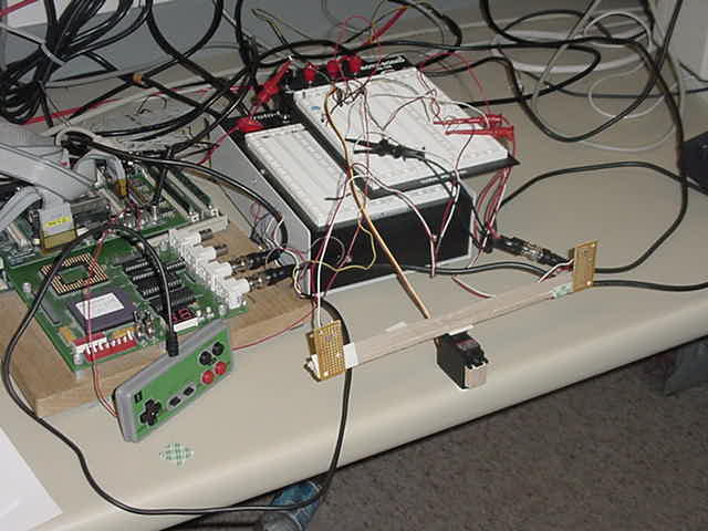
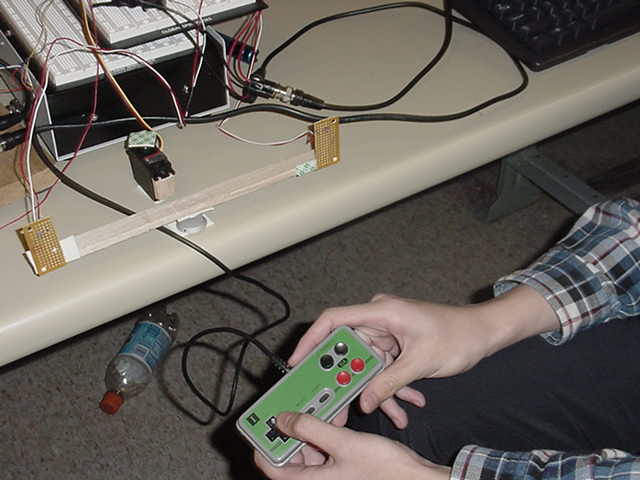
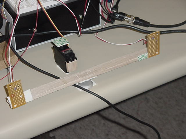
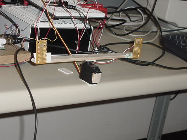
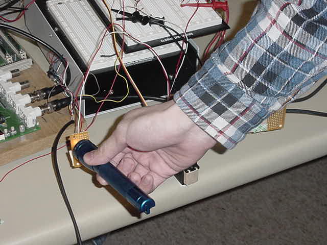
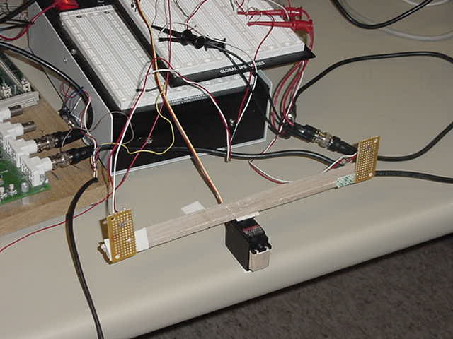
Media
Photos:
Video:
![]()

References
Nintendo Controller spec:
EECS270 spring 2005 lab
webpage:
http://www.eecs.umich.edu/courses/eecs270/lab/s05_lab7.pdf
http://web.mit.edu/tarvizo/web/nes-controller.html
Photo resistor and servo motor
spec:
EECS373 Fall 05 project
overview slide:
http://www.eecs.umich.edu/courses/eecs373/Labs/373%20PO.pdf