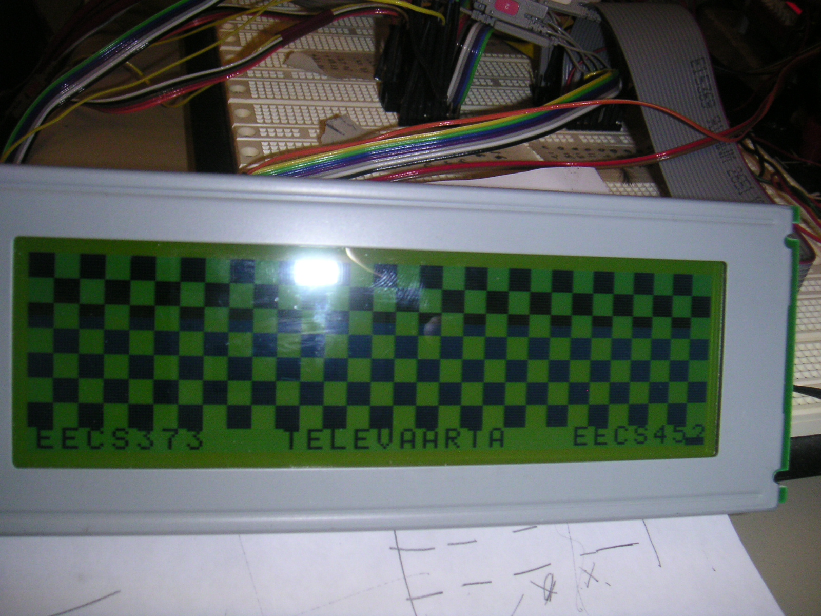
TELEVAARTA
by
Vinayak Aggarwal and Mayank Singhi
EECS 373 Fall 2005
_______________________________________________________________________________________________________________________________________________________
Introduction
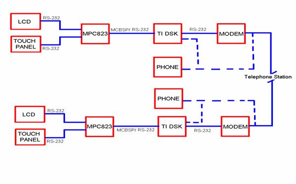
Our main goal was to design a graphic interface for phones, for example, an LCD, for digital exchange of data in addition to voice. Using this device, one would be able to send and receive emails, have live whiteboard conversation and transfer data without computer and internet over a normal voice channel. This involved compressing voice so that other data could be send along with the voice. We implemented the voice compression part of the project in EECS 452. The compression technique we used is Adaptive differential pulse code modulation (ADPCM). The basic outline of this product is described below in the following figure
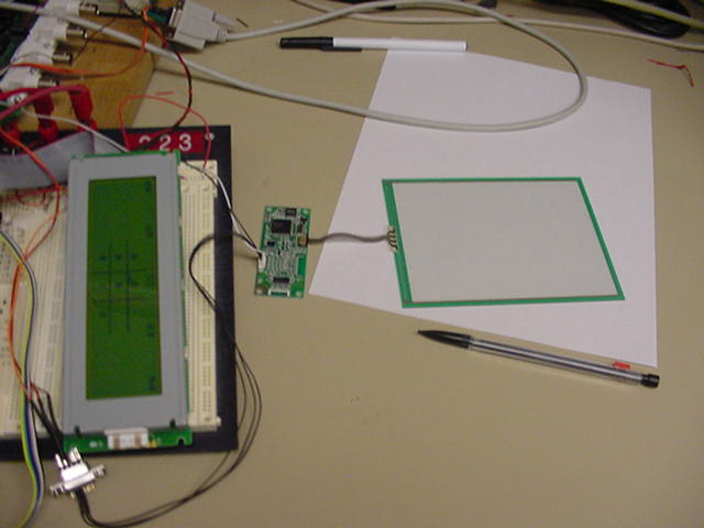
This EECS 373 part of the project involved interfacing the LCD and touch panel to each other using the MPC823 processor. The goal was that whatever one writes on the touch panel would come on the LCD. We also added some features like eraser, game and a clock on the LCD.
High Level Design
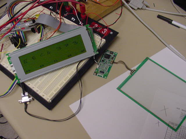
We interfaced the LCD and touch panel using the mpc823. We added a menu bar on the LCD, which has options like "pen", "eraser", "clear", "game" and "clock". To enable any of these features, one needs to bring the cursor on the particular option and press the push button 1 on the board, just exactly like we do it on windows (bring the mouse on the option and then click it).
Pen: This is the default option selected when we begin. This option enable the pen and so whatever you write on the touch panel would come on the LCD
Eraser: This option enables user to erase whatever the user has written before.
Clear: when clear option is selected, it clears the whole LCD display except the menu bar.
Game: We implemented the game of tic tac toe on the display, so when this option is selected, the game begins.
Clock: We added an analog clock on the LCD which ticks every second and if this is selected, it turns into digital and vice versa.
The major components involved in this project are as follows:
The DMF5005N LCD
This is a 240 X 64 pixel
graphic LCD. It has an in-built LCD controller t6963c, a display RAM, a
character generator ROM and drive circuits. The most important part to
interface it with mpc823 was to get the bus timings correct and understand
to how to talk to the controller.
The touch panel
We got this touch panel from Fujitsu. This was a 4096 X 4096 pixel resistive
touch panel (N16B-0558-B230).
This also had an in-built controller but it was really difficult to
understand it since there was no documentation available.
The Serial Port
The communication between
the touch panel and mpc823 was done through the serial port. It involved
changing the baud rate in the serial port's driver to communicate
effectively with the touch panel.
Hardware Design
The interface to the LCD was designed in the hardware. All the timing issues
important to the LCD were taken care in the hardware design using xilinx. The
touch panel was connected to the mpc823 through the serial port. The touch panel
and the mpc823 had a female port so we needed a male to male cable which we
could not find, to come over that, we connected the individual pins of both the
ports to their respective ends. We also implemented the hardware to generate an
interrupt which was used to make the clock tick every second. We used the
display processor to display both graphics and text. We implemented the menu bar
on the LCD using the text characters stored in the character generator ROM. The
mapping of the touch panel coordinates on the LCD was done using graphics.
Software Design
Most of the software
design was implemented in C and some functions were implemented in assembly
which involved extensive use of EABI, for eg. to convert the coordinates of the
touch panel into the lower and higher byte of the address to map the coordinates
on to the LCD. All the initializations for the interrupts and timers, the
interrupt handler were done
in assembly.
The interrupt was generated every second and the interrupt handler was called,
the interrupt handler would keep updating the graphical area of the LCD to show
the clock ticks every second.
When any of the option on the menu bar is selected by pressing the push button
1, the appropriate C function is called to perform the required task. The
interface for the push button 1 is implemented in the hardware. To write any
data or command to the LCD, we need to check the status of the LCD. While
checking the status we also keep checking if the push button 1 is pressed or
not, in other words this can be described as polling.
One of the problems we had was that, on the LCD, we could write 1 byte at a time
and when we try mapping the touch panel coordinates on to the LCD, only single
dots would appear on the LCD in a discrete fashion and not in a continuous
manner. To get around this, we created a static memory which kept storing
whatever was written previously on a particular byte and then keep ORing with
the new data. This way, we were able to map the coordinates on the LCD in a
continuous manner.
Results of the Design
After much hard work and effort, our design worked the way we expected. The major problem we had was to understand the working of the touch panel. We did not had any proper documentation for the controller board which came with the touch panel. We did not know what kind of data was coming out of the touch panel. To understand the touch panel, we connected the touch panel directly to the computer's com port, this way we thought we will be able to see what kind of data were we getting from the touch panel on the hyper terminal. We did get some data on the hyper terminal but it was not in a readable format, the windows hyper terminal kept showing some random characters which were not making any sense. Therefore, to understand that data, we downloaded a software called indigo which showed the data coming in from the com port in hexadecimal form. After understanding the data received, we came to know that we were getting a header data followed by four 8 bit data for the coordinates. Then we were able to map these coordinates on to the LCD.
Media
Picture 1
Picture 2
Picture 3
Video coming soon