EECS 373, Fall 2006 - Final Project
Hardware Accelerated Chess Engine
AJ Frantz
Tarik Ourchane
Introduction
Chess is a game which is inherently difficult to
write an artificial intelligence for. The most widely recognized
method for using a computer to compete in a chess game is to brute
force all the possible positions to a certain depth, and then choose
the best possible course of action. The effectiveness of this
algorithm is highly dependent on the depth that can be achieved--that
is, a program which can look 3 moves ahead is vastly inferior to a
program that can look 8 moves ahead. The majority of time in such
a program is spent generating and sorting possible moves, and
evaluating positions is also time consuming. However, move
generation and position evaluations are highly parallelizable problems,
which allows them to be executed in hardware extremely efficiently,
thus increasing the maximum depth (and thereby the effectiveness) of
the program. This is the approach taken by several chess modern
chess computers, including IBM's famous Deep Blue. We endeavor to
create a chess engine that uses such hardware acceleration.
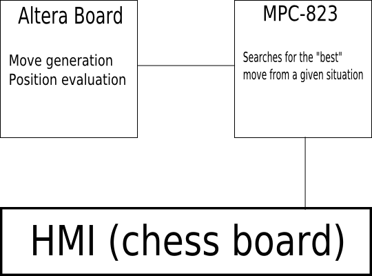
High Level Design
A hardware accelerated computer of this type
consists of 3 main parts: 1) an interface, which allows moves to be
input, 2) a searching component, which attempts to find the best move,
and 3) a move generator / position evaluator which executes the time
consuming parts of the search described in component 2.
Member Task Distribution
Interface from standard chess GUI to internal command format - AJ Frantz
Alpha-Beta (minmax variant) search execution - Tarik Ourchane
Interfacing to specialized chess hardware - Tarik Ourchane
Implementation of specialized chess hardware - AJ Frantz
Hardware Design
The hardware that we designed consisted of two main
parts: the board interfacing used to connect the Altera DE2 board's
larger FPGA to the MPC 823 and the actual chess hardware itself.
The board interfacing was implemented as a set of
synchronized registers, one 8-bit wide register used for communication
from the MPC823 to the Altera FPGA and one 17 bit wide register from
the Altera FPGA to the MPC 823. These registers were built by
connecting GPIO pins from each board together as the "data" bits and
then setting aside one bit for each register to act as a "latch" line.
This way, when the registers were written to the data lines would
go to their appropriate values and the latch line would cause register
synchronization to occur.
The chess hardware was written entirely in Verilog.
The logic was built according to the research paper on FPGA move
generation found in the references below. Basically, a Verilog
module describing a chess square was created. This module was
instantiated 64 different times with a parameter to tell each
instantiation which square on the board it represented. When the
logic received a command to generate a move, it went through 3 steps.
First it would turn on a set of "transmitters" for each piece on
the board from the side to move. These transmitters were
connected to the squares that a given piece could move to. All
other squares then turned on their "receivers." When a receiver
registered a hit (that is, on of its incoming lines became asserted)
the square being hit would apply for "arbitration."
Arbitration consists of sending your piece type and
square number into a 6-level binary tree of Verilog modules that take
in two inputs and output the piece and square with the greater material
value (as in a Queen is more valuable than a pawn, etc.). At the
top of this arbitration tree then appears the square number and piece
type of the most valuable victim. The greater value piece is
chosen because the order in which you search
moves is highly important to reducing the width of the move tree that
must be searched in our software, discussed below. The process is
repeated to find an attacker, only this time the victim turns on all
available transmitter lines (as opposed to just the lines appropriate
to its piece type, as happens above) and only pieces that can move turn
on their receivers. Applications go through the arbiter tree and
again we produce the most valuable attacker that can attack the most
valuable victim.
The final stage of move generation was actually
making the move. This is a fairly simple operation of copying the
piece type from the source square into the destination square, clearing
the source square, and setting a mask bit so the same move is not
generated twice. Evaluation of positions happened much the same
as arbitration, however rather than choosing the higher piece value, an
evaluator sums the values of pieces.
The chess logic also integrated with two major components on the Altera
DE2 board: the SRAM chip, and the character LCD. The SRAM chip is
used in the chess logic to store the list of moves that have been made
in the searching process so far. This list is kept so that the
board can be reverted to its true "game state" after a search for the
best move has been completed, and indeed so that individual nodes of
the search can be partially reversed to search a full tree without
having to remake each move in the tree each time.
The character LCD then displays the next 3 moves that our chess engine
is considering making. These values are pulled from inside the
SRAM chip, which is at the same time being accessed by the chess logic
itself, so an arbitrated bus was was developed to coordinate access
between the two functions. The character LCD was a simple
HD44780-based controller so there was a great deal of standard
documentation available for reference. Modules that refreshed the
data on the character LCD and pulled new data from SRAM were
developed to achieve the desired goals in this area.
Finally, due to the chess logic not being entirely functional during
the demonstration we opted to replace the logic with a simple move
lookup table that translated a move number in a chess game to a
scripted move. This way we were able to demonstrate that our
interfacing all worked, despite difficulties with the chess logic.
Software Design
For the PC side of our project, we wrote a simple wrapper application
that spoke to the chess interface using pipes and standardized ASCII
commands and converted those commands from the interface into a much
more compressed commands that got passed to the MPC 823 over RS-232.
Our software was ABI compliant and
made use of both interrupts and the real time clock. Our software
was setup to interrupt in two situations: when we received data from
the chess interface via the RS-232, and every three seconds (via the
RTC) to return the move we decided on. Inside our ISA we initiated
different functions depending on what we received via the RS-232.
Our software
contained two C functions and nine assembly functions. The first
assembly function was used to set up the RS-232 port and interrupt
whenever we received data. The next assembly function was created to
utilize the Real Time Clock functionality of the MPC. This function
started the RTC and enabled the clock to “alarm” or interrupt
every three seconds after we had been told to make a move.
The next six
assembly functions all deal with the chess game mechanics. The first
was a new game function that when called sent a given command to the
Altera board letting it know that new game has begun, and to reset
the board. We also had a function that made a specific move that
either we chose to make or that we received from the chess interface,
a function that told the Altera board to generate a legal move and
make it, a function that read the evaluation for a given move and a
function that told the Altera board to unmake a move. When sending
commands to the the Altera board we always write or pass the
operation to the Altera board via the M2A (MPC to Altera) register.
The last piece of
assembly code we wrote was our ISR (interrupt service routine). The
ISR handled the two interrupts I previously mentioned above. When we
received an interrupt from the RS-232 port indicating that we
received data, we set our “thinking” flag and called the
appropriate function (new game, make move, make specific move, etc).
We also started our real time clock and set it alarm us in 3 seconds.
When our timer interrupts three seconds later it clears the
“thinking” flag, and we read our A2M (Altera to MPC) register to
retrieve the move our board has decided upon. We then send this move
both to the Altera board to update its board status and to the chess
interface.
The two C functions
were an alpha beta search and an initial search algorithm. The
initial search was called in our program main once our thinking flag
was set. This would in turn call our alpha beta search as long as we
were still “thinking” or within our given move time. The
alpha-beta search algorithm would continually tell the chess engine
to make, evaluate and unmake moves, until we had found the best
possible move in our restricted time. However, in the final design
of the project we decided to remove this search algorithm and just
query the Altera board for the next move in a scripted sequence that
was stored in the FPGA.
Results of the Design
While all of the integration of hardware and
software components worked as expected, the chess logic that we
attempted to implement did not work as expected. Judging by the
research being in this field it is likely that simply implementing such
logic is an entire project in and of itself. That said, we did
successfully develop a platform upon which this research could take
place. In the end we were able to demonstrate our platform
replaying a scripted series of games, but there is no reason that the
lookup table of scripted moves could not be drop-in replaced by the
chess logic of a researcher and work as we had originally intended for
the project.
A painful restriction in getting the chess logic to
work was the inability for the free web downloaded version of Quartus
II to use incremental compilation. Without this feature activated
a compilation of the chess logic, even after only a very small change,
took nearly 40 minutes. This severely hampered our efforts to get
the chess logic portion of our project working.
Conclusions
While more processing power helps a chess engine in
any situation, ours was much more a problem of implementation than it
was a lack of hardware. We simultaneously underestimated the
amount of work that was required to implement the chess logic and
overestimated our experience and knowledge of Verilog. If we
could go back and time and advise ourselves of how to approach
this project we would suggest a much more thorough simulation of
each Verilog module, and perhaps reading a book on Verilog to better
understand how we might implement the logic with the intent of writing
less C-in-Verilog-type code.
Still, we are proud of the platform that we created
and perhaps after the Verilog experience that a future semester of EECS
470 there may be an attempt to implement the chess logic, now that
we have demonstrated that the platform is viable.
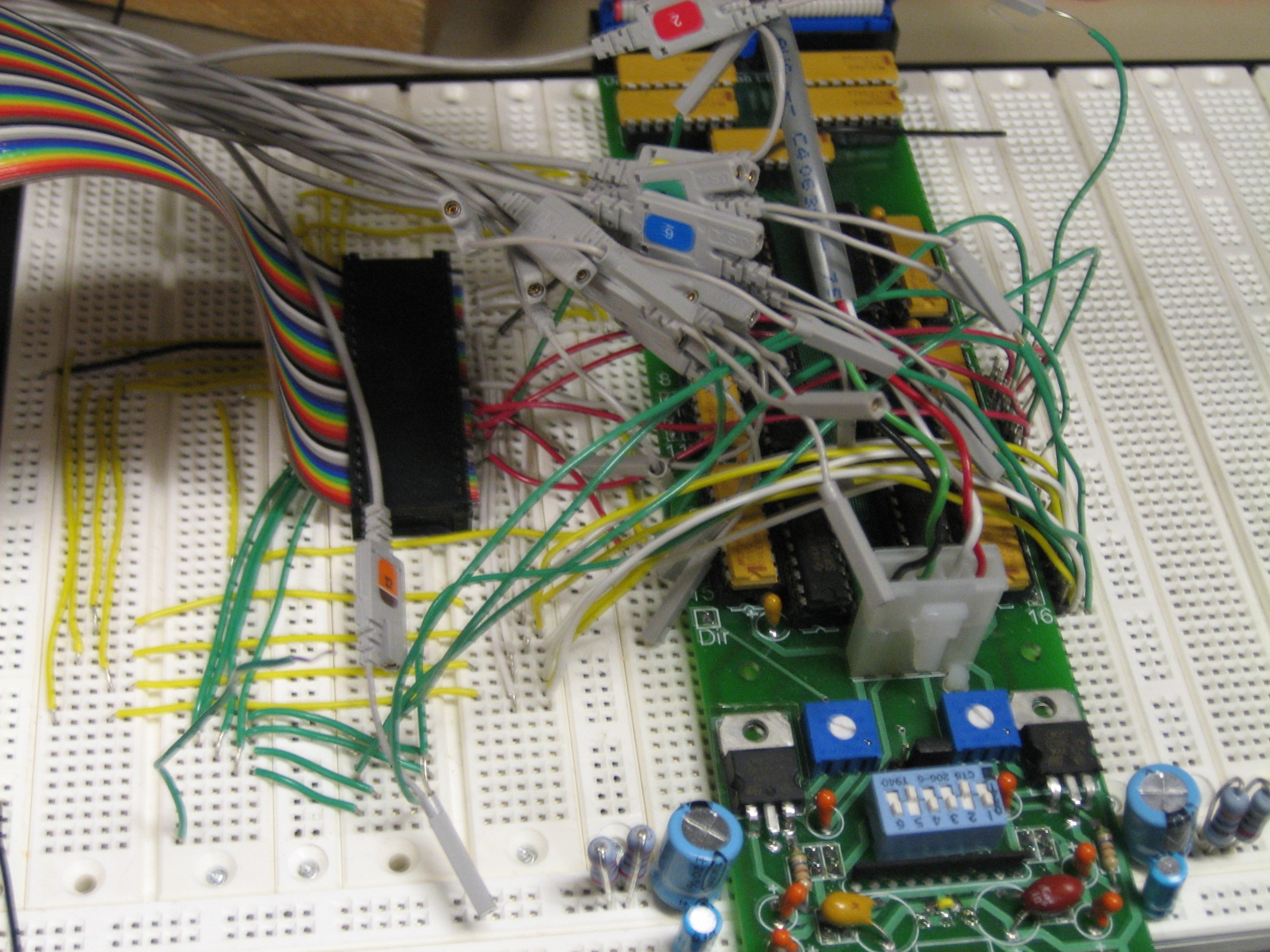
Media
The expansion board breakout that interfaced the MPC-823 and the Altera
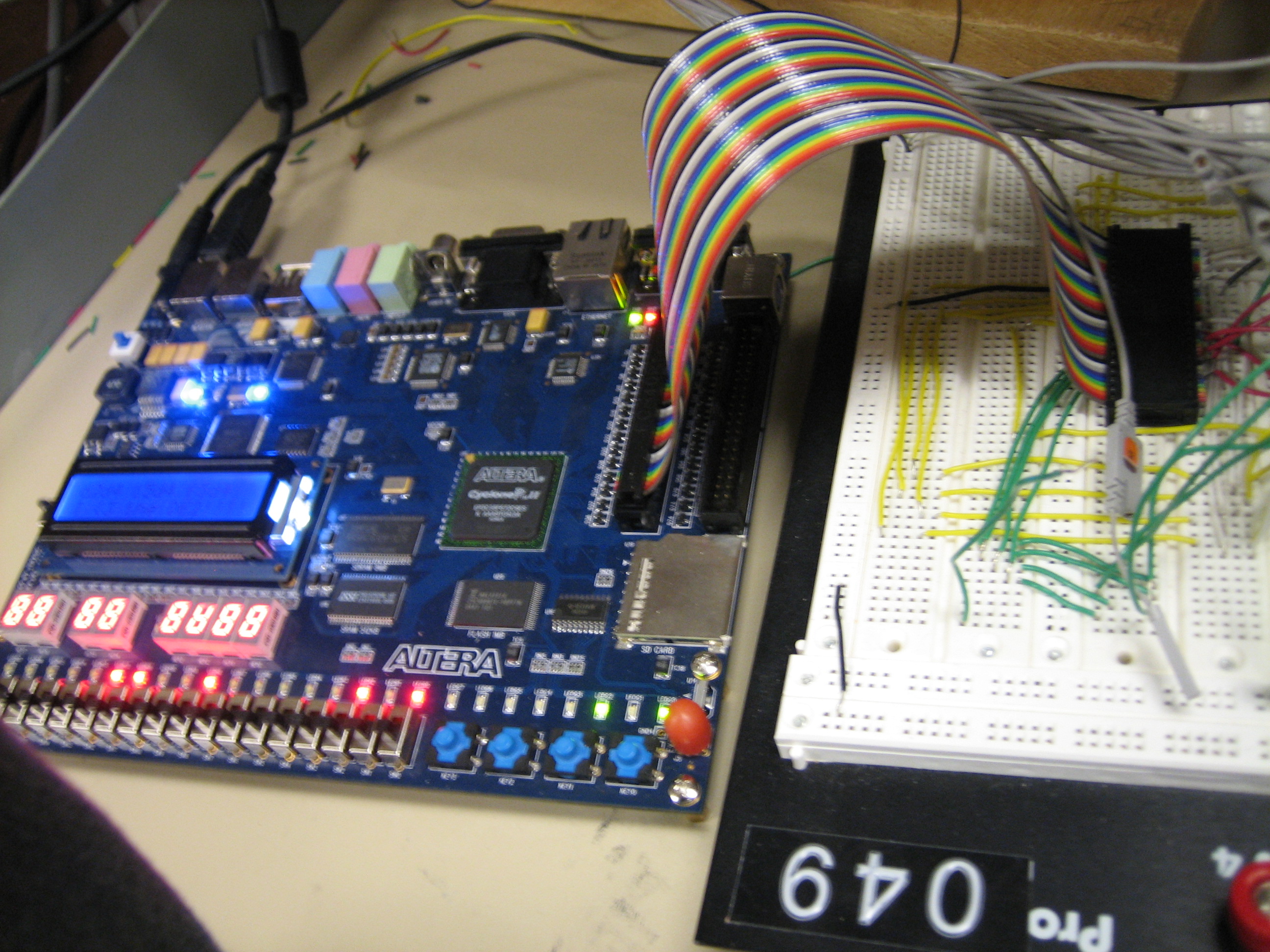
A better vantage point of the interconnection between the expansion breakout and the Altera board
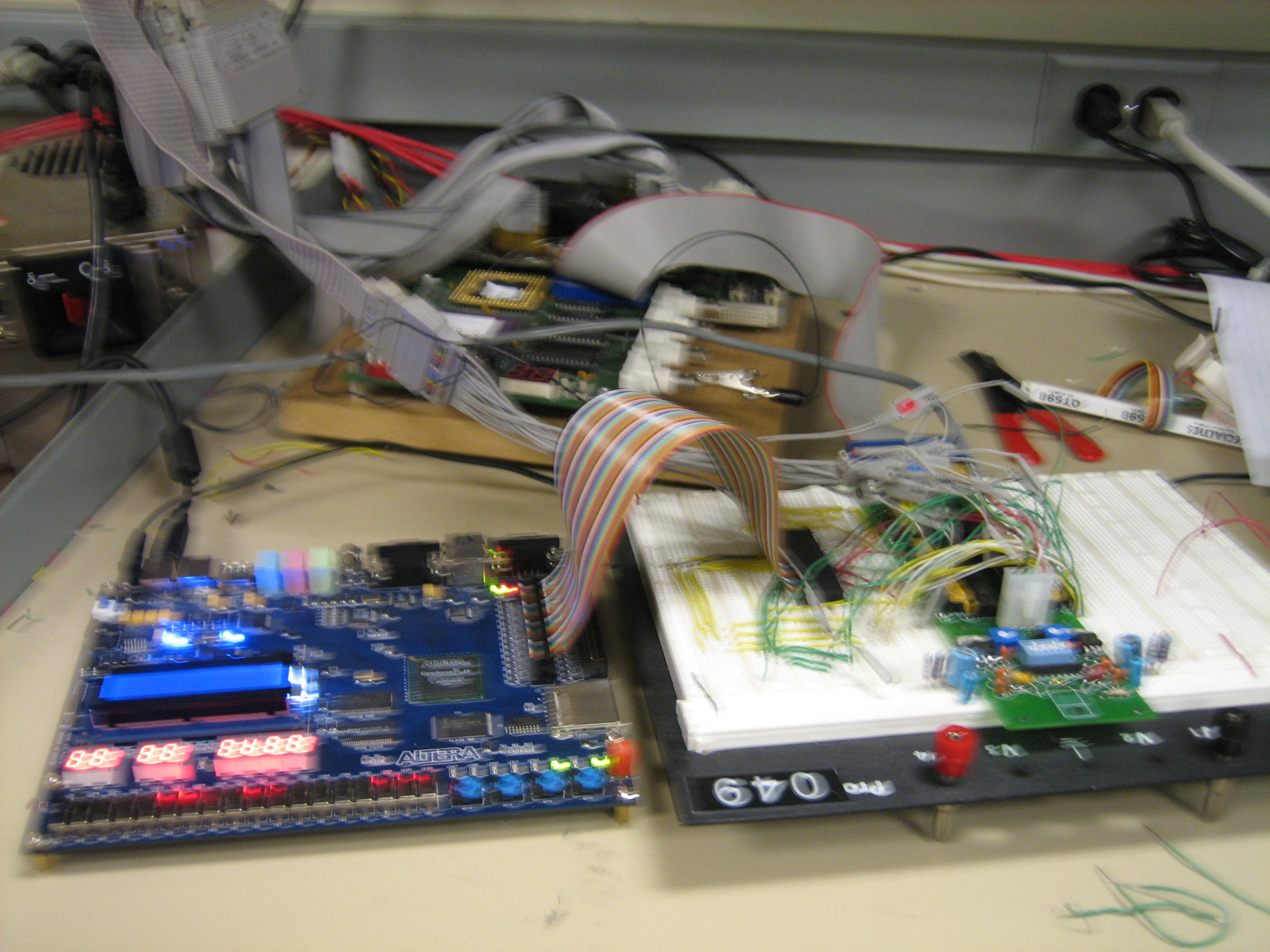
The overall system
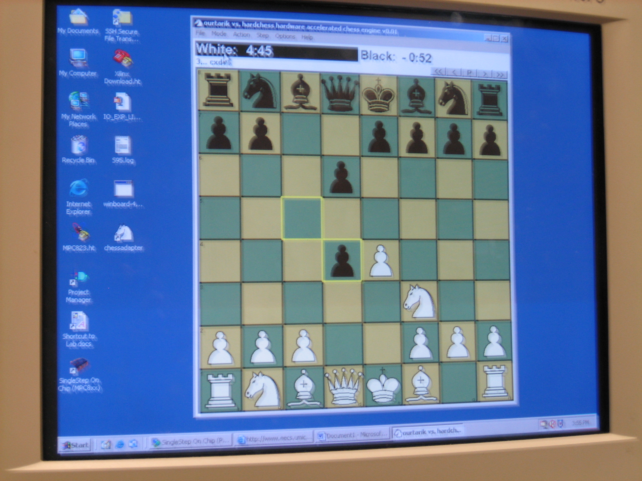
What a user would actually see while playing against our program
Click here for a brief demo clip of our engine playing a game
References
Altera Resources
Introduction to the Quartus II Software -
http://www.altera.com/education/univ/materials/manual/labs/tut_quartus_intro_verilog.pdf
DE2 User Manual - http://www.altera.com/education/univ/materials/boards/DE2_UserManual.pdf
Character LCD Resources
How to control a HD44780-based character LCD - http://home.iae.nl/users/pouweha/lcd/lcd.shtml
Chess Resources
An FPGA Move Generator for the Game of Chess - http://www.macs.ece.mcgill.ca/~mboul/ICGApaper.pdf