EECS
373 - Final Project
Fall
2006
Title
Nuclear Launcher
Members
Naser AlDuaij
-
alduaij@umich.edu
Tarik Metti
-
tmetti@umich.edu
Arvind Shenoy
-
shenoyas@umich.edu
Introduction
Our goal for this project was
to create a launcher that can be controlled to move left, right, up, down, and
shoot a ping pong ball with a Nintendo controller. The second part of this
project is to interface a sensor so that it auto-calibrates itself to a
specific target in a 3ft to 10ft range on a push of a single button. In
addition to this, there will be an LCD that will display a welcome note and
eventually the distance of the closest target in the sensor's range. We will
use a simple Toys'R'us launcher mounted on a trebuchet that will rotate. The
user will chose a target horizontally and press a button where it will
auto-calibrate and let the user shoot it.
High Level Design
For the auto-calibration we
sampled 20 sensor readings and then took the median of those readings, and with
that we got really accurate results. We also made some measurements at each
point to determine the distance that the launcher will shoot according to the
sensors and we calibrated it so that it would give the correct results.
The other parts of the project such as turning the launcher in different directions
are mostly mechanical.
Interfaced Components:
LCD Character Display: Displays a welcome note
and then displays the current distance of the closest object and warns when the
target is out of range.
Nintendo 8 controller: Controls the launcher (up,
down, left, right), shoots the ping pong ball, and allows for switching to
auto-calibration mode.
Ultrasonic distance sensor: Calculates distance
to the target from the launcher.
Gear motors: Used to control the horizontal and
vertical motion of the launcher as well as firing.
H-Bridges: Used to control the direction of the
rotation for the motors.
Motorola MPC823 Power PC processor and Xilinx
FPGA.
Member Task Distribution
Naser AlDuaij: The
hardware/circuits guy.
·
Worked on the hardware for the ultrasonic sensor, LCD,
and Nintendo controller.
·
Did the circuitry for the components and the expansion
board.
·
Helped with building the launcher.
·
Helped with calibration.
·
Debugged various software issues.
Tarik Metti: The
mechanical guy.
·
Designed and implemented the launcher as well as its
mechanics
·
Worked on LCD and ultrasonic sensors.
·
Worked on software and the final integration of the
components.
·
Calibrated the launcher.
·
Debugged various hardware and software issues.
Arvind Shenoy: The
software guy.
·
Worked on the software and the final integration of the
components.
·
Worked on LCD and the Nintendo 8 controller.
·
Helped with the circuitry.
·
Calibrated the launcher.
·
Debugged various hardware issues.
Hardware Design
Nintendo Controller:
The Nintendo Controller was interfaced using counters to generate a clock
with a 10 microsecond period, using that clock a latch pulse is generated every
3 milliseconds. After the latch is generated, a counter counts to eight
generating eight other pulses. The shift register is then enabled once the latch
is sent, the received data is then shifted and finally latched after the last
pulse. The Nintendo Controller is memory mapped to address 0x02600000, where the
user can easily read the data latched by the shift register and can deduce from
the bits which button or buttons were pressed.
Test point 1: Latch.
Test point 2: Pulse.
Test point 8: Data Input.
Gear Motors:
The gear motors are memory mapped to address 0x02600008. Once the user writes
to that address the data will be sent to the test points which are indirectly
connected to the gear motors.
Test points 2/3: B/Start.
Test points 6/7: Left/Right.
Test points 14/15: Up/Down.
H-Bridges:
The 3 H-Bridges serve as a connection between the test points and the gear
motors. It defines a direction for the gear motor to rotate, for example writing
a 0x01 to address 0x02600008 would drive the motor to rotate clockwise (12
Volts), writing a 0x10 on the other hand will cause it to rotate
counterclockwise (-12 Volts). Giving us the possibility of rotating the launcher
360 degrees and aiming it from perpendicular to the base down to about 40
degrees. The H-Bridges inputs are test points 2/3, 6/7, 14/15.
LCD:
The LCD is memory mapped to address 0x02600004. Once the address is written
to and TA* is asserted, the data to the LCD (PD_IN[31:24]) is latched to the
test points and the PD_IN23 is driven to the RS pin of the LCD. RS is latched
using LCD's clock and shifted/combined to meet the typical 500ns time
requirement. The enable signal is delayed by 2.5 microseconds since that's the
maximum time for every transaction. The RD/WR* was directly hooked up to GND
since we are always writing to it.
Test point 16: RS.
Test point 17: ENable signal.
Test points 18-25: LCD Data (OUT).
Ultrasonic sensors:
A write to the address 0x0260000C will generate a trigger pulse. After the
address is decoded and TA* is asserted, it uses a counter to generate a 100
microsecond wide trigger pulse. The returned echo pulse is used to enable a
counter, that counter value will correspond to the distance (1 increment is
equivalent to about 41.7 nanoseconds). Once the echo is deasserted it sends a
latched one to IRQ7 interrupt, this tells us that the counter value is ready to
be read. After a read from address 0x0260000C the tri-stated counter value (a
32-bit number) is sent to the processor. The IRQ7 interrupt is cleared by
writing a 0x00000003 to address 0x03300000 and the counter value is reset on the
next trigger pulse.
Test point 12: Trigger Pulse.
Test point 11: Echo Input.
Main Design:
We interfaced the Nintendo
controller to be memory mapped, so we can read 0x02600000 to see which buttons are
pressed. For the motors we simply use an
H-Bridge for up and down, another H-Bridge for left and right, and a third
H-Bridge for shooting and releasing (B and start). Select is used for sampling
and 'A' is never used. The gear motors are hooked up straight to the test points
from the H-Bridges and the software had to write a value to 0x02600008 in order
to generate a signal that would drive the corresponding motor (and its
direction). The LCD was also memory mapped to 0x02600004 where we had the
hardware generate the correct timing for each signal to write to the LCD.
Finally, writing to 0x0260000C will generate a pulse and the counter will start
counting when receiving an echo pulse. When the data is ready an IRQ7 interrupt
is generated indicating that the measurement is ready and can be read from the
same address.
Software Design
Initialization Code:
The initialization code to set the launcher and the hardware to a known
state was done in an assembly function (init()). This function was called by
our main function in the C code. The initialization function included
initialization for the timers, the interrupt registers, code to initialize the
LCD display, and initialization for the memory that we were planning on using.
The initialization function was ABI-compliant.
Device Drivers:
LCD Character Display: The software
that was written for the LCD contained a C function (print()) and an
ABI-compliant device driver (lcd_putchar.s) written in assembly that would
output a single character to the LCD. When print() was called to output a
message to the LCD, the message would immediately be buffered to the memory. The
routine lcd_putchar was then called once every 3.2 milliseconds (as specified
by our timer) to meet the timing constraint of the LCD display. The timer would
throw a LVL4 interrupt every 3.2 milliseconds and the ISR routine would in turn
run code that called the device driver to output one of the characters. The
character that would be displayed was controlled by an internal counter that
counted from 0 up to the length of the string.
Timer Implementation:
One of the main problems we encountered while doing the project was that the
two timers that are provided cannot throw 2 different interrupts since the CICR
register only allows for one interrupt to be thrown. Therefore, we decided to
throw a LVL4 interrupt ever 3.2 milliseconds and added internal counters that
would keep track of how many LVL4 interrupts were thrown and would branch to
other functions as needed. This allowed us to implement various timings for
different devices using just one counter. An alternative way to approach the
problem would have been to read the CPM registers to find out which interrupt
was thrown.
Ultrasonic Sensor:
In order to get the ultrasonic sensor to get us accurate and precise
readings, it was important for us to sample lots of data. The ultrasonic sensor
often varied from reading to reading. Therefore, we stored readings from the
ultrasonic sensor every 64 milliseconds and stored the median in the memory.
The median function was written in C and it would simply take the data, load it
into an array, and do a simple O(n log n) bubble sort on the data before
finding the median. Thus, the median was always the distance value used by the
software for the launcher.
Auto-Calibration Implementation:
Moving the launcher based on the data gathered by the ultrasonic sensor was
one of the main challenges of this project. The launcher would move up or down
in units of “ticks” which ¼ inch increments. The launcher would find the median
distance from 20 samples and would use that distance to find out how many ticks
to move based on data that we gathered from calibrating the launcher. It would
also keep track of where it was and would move up or down depending on the
distance of the next target.
Main Design:
The main software design of the launcher consisted of a main function that
had an infinite loop in which it would perform a read from the address of the
Nintendo controller and write to the address that the motors were memory-mapped
to. However, to allow for auto-calibration without any interruption from the
user, we added a condition to check if select was pressed so the motor address
would not be over-written with information from the Nintendo controller while
performing its automatic calibration. While in auto-calibration mode, the
launcher would check the distance of the object and check against the data we
had collected from our calibration measurements to figure out how far to move
up or down.
Results of the Design
Our design mostly worked as
planned, but we had a few compromises. We were aiming for 360 degrees rotation
but we settled for 180 degree rotation because of the wires. Secondly, we
wanted to auto-calibrate horizontally to a target but that couldn't be done
since the gear motors to rotate it left and right weren't stable (they keep
slipping, and the time to rotate x degrees varied from time to time). Although
the sensors worked perfectly for a 3ft to 10ft range but we had to stick with
that instead of a 0ft to 15ft range because of the limited space in lab and the
inaccuracy of the sensors. Fortunately, there were no unresolved problems in
our design. The LCD displayed the distance accurately, the Nintendo controller
steadily controlled the launcher, and the auto-calibration system worked
accurately and precisely as planned.
Conclusions
We were able to implement our idea with the components. Our launcher was
precise and accurate to 0.5 ft. We did not need more processing power but we
needed more high quality motors and high accuracy sensors. We would have
changed the way that we controlled the launcher horizontally, although there
was no problem with the Nintendo controller controlling it left and right but
it could not have been possible with horizontal auto-calibration since it kept
slipping. We would have wanted to get a higher quality motor or used another
method of controlling it left and right. Our project went well as planned and
we learned a great deal about the components, reading specifications,
interfacing, and most importantly integrating components together.
Media
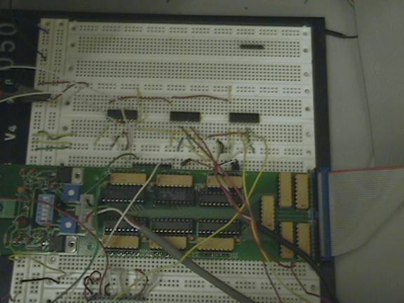
Our expansion board and the setup of H-Bridges:
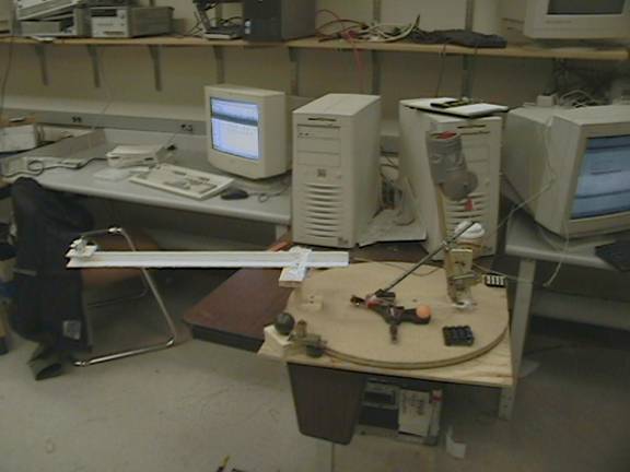
The launcher at its initial position:
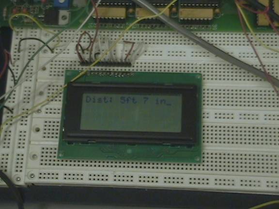
The LCD character display outputting the distance from the launcher to the
target in feet/inches:
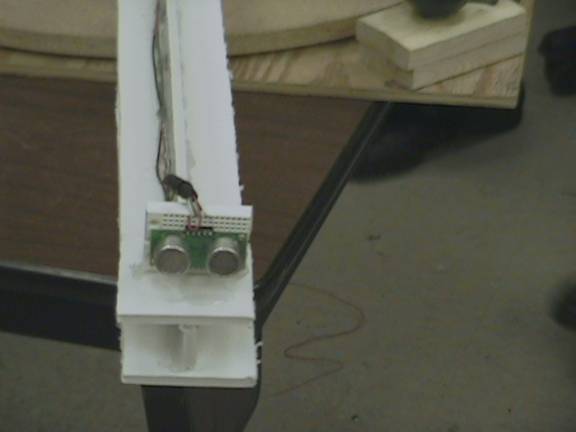
The ultrasonic sensor mounted on the front of the launcher:
Video
of the launcher in action
NOTE: Xvid codec is needed. It can be downloaded at
http://www.koepi.org/xvid.shtml
Appendix
Source code for
Ultrasonic Sensor module (we didn't get to use it)
References
LCD interfacing
Nintendo
8 interfacing
Ultrasonic
Sensor module