Hacking a printer: the plotter files
Members:
Matt Blythe
Pat Quinn
Introduction
The overall goal for this proect is to make a device that can use a pen to write and draw. Specifically, we wanted to be able to type into a keyboard, and have out plotter print out our text for us, or be able to use the arrow keys to move then pen around a page as we wish.
High-Level Design
The general subcomponents of our design include the plotter device itself (including two stepper motors, and a servo motor) and its associated electrical circuitry, a PS/2 kayboard, the FPGA (containing the logical hardware to read from the keyboard and control the plotter device), and the MPC823. They interact as seen in the following diagram:
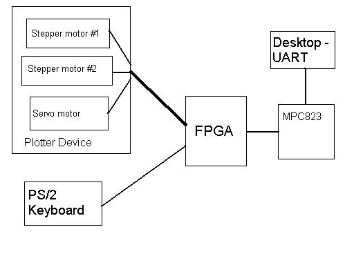
Since we did not use specialized stepper motor controller ICs, we had to design our own controller in hardware that could move each stepper motor both a relative distance or to an absolute position. This also involved producing the correct phasing of current on the two (or four) coils of each stepper so that it would move properly.
Member task distribution
Since this was a project group of two, it was not infeasible to only work on the project when we were both available. Generally, both of us contributed about the same amount of work in design and debugging of each component.
Hardware Design
Th functions we implemented in hardware included two stepper motor controllers, a PWM generator to drive our servo, and a PS/2 host controller for the keyboard.
Stepper motor controller
this controller allowed for relative or absolute movement by reading a specific bit of the memory-mapped input. Several more bits were used to specify the value. In the case of a relative movement, the value was added to the current position to specify the future position. In the case of an absolute movement, this value was taken directly as the future position. We then compared the future position value to the current position value. If the current position was greater, we continued to decrement it, and if it was lower, we incremented it. the lowes two bits of the current position drove a 2-to-4 encoder, which provided a one-hot signal to the current bufferring circuits to actually drive the steppers. We also constructed large clock dividers in hardware so that the stepper motor could keep up with the current position. Once the current position equals the desired position, it signals an interupt to the processor.
PWM generator
The design of this generator was very similar to the design discussed in class. We used a fixed clock frequency, but then read a value from memory-mapped I/O to determine the pulse width. Again, we constructed clock dividers in hardware.
PS/2 for the keyboard
We found a design for a PS/2 host controller in VHDL, so this gave us a starting point for creating one in verilog. What the controller does is it sample the PS/2 clock line every processor clock cycle, and if the PS/2 clock line is constant for 8 samples, it stores the clock line into a filtered clock register. On the negative edge of this filtered clock register, it samples the data line. After receiving a start bit, 8 data bits, a parity bit, and a stop bit, it puts the 8 data bits into an output register and signals an interrupt to the processor. When the register is read, it clears the interrupt and waits for another keyboard scan code.
Software Design
All software events, save initialization, are interrupt-driven. Latancy time in the plotter device is taken care of in hardware. Once the plotter is in the proper location, it will interrupt for it's next position. Since the hardware doesn't know where the servo motor is, we have a delay built into hardware to anticipate that.
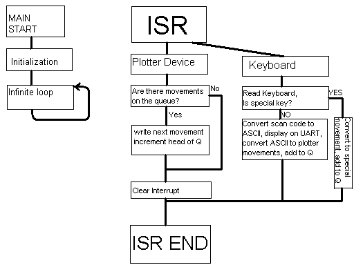
We used assembly for the majority of the code, except for the conversion tasks. We had C functions to convert from scan codes to ACSII (or special movements in some cases), and C code to convert from ASCII to plotter device movements. All device movements were coded into a 32-bit line, so all three motors could be controlled in one write. Below is the general flow of our software:
Results of the Design
The only design problem we really had was getting negative relative movements on our stepper motor drivers. We resolved this by reducing the the number of bits used to store the current position for the vertical movement. While there are no unresolved problems with out design, we would have liked to add an LCD, so that the whole system could work independant of the PC. Right now, we still display the characters that we are going to print on the UART interface.
Conclusions
It is possible to implement the idea with our components, and we believe that we did just that. The amount of processing power we have is appropriate, but we have noticed that our ISR has a fair amount of latency associated with it. If we could start over, we would probably spend more time to make more robust software.
Media