POV Writer
Project By:
Christopher Danks
Andrew Phillips
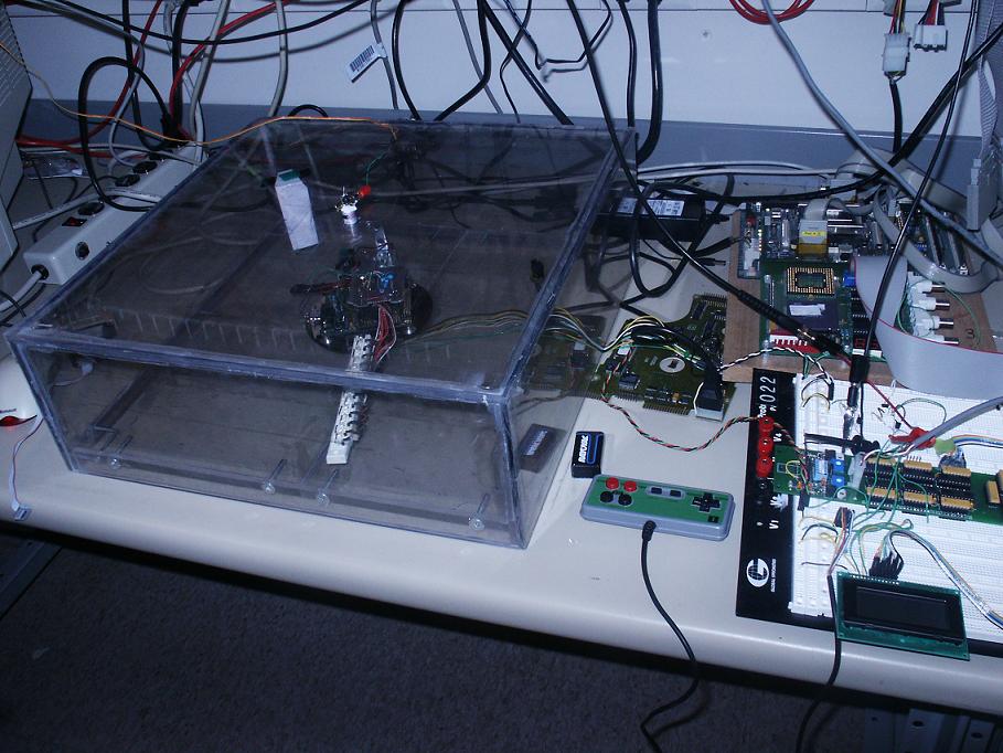
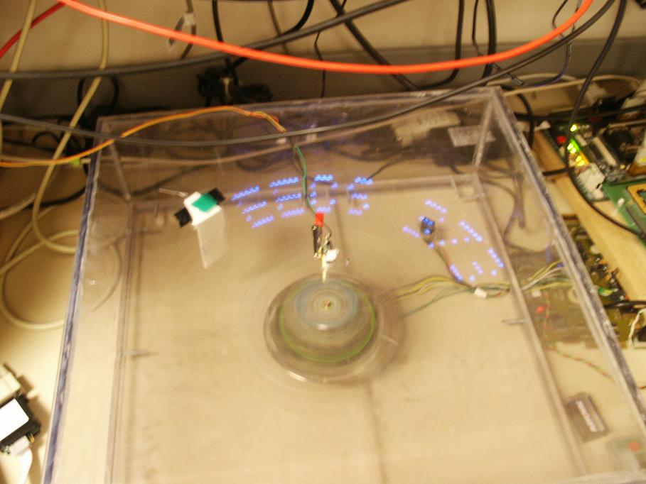
Our project implemented a two dimensional graphics display utilizing a single linear array of LEDs. By rapidly rotating the LED stick around a fixed point and changing the output of the LEDs, we were able to generate what appeared to be a real, two-dimensional image, thanks to persistence of vision. The speed of the motor for the display wheel and the image on the display were controlled by the user with a game pad and LCD interface.
Overview
We used Pulse Width Modulation to control the speed of the motor for the display wheel. The motor we selected was a stepper motor from an old hard drive, so we couldn't control the motor directly with PWM. Instead, we used the original control board from the hard drive and modified it slightly to accept our PWM input instead of the original control signal from the board. A feed-back loop from a sensor was used to give the our motor controller information on the current speed of the motor.

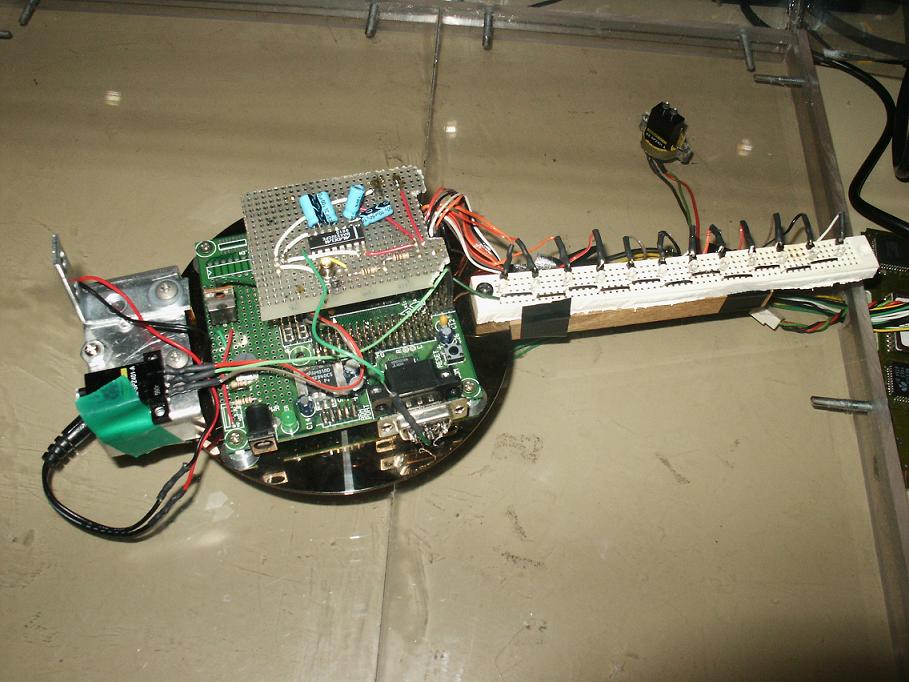
The components for image processing involved a sensor to determine the speed of the wheel for the MPC 555. This information was used to control the refresh rate of the display (how quickly the LEDs turned on and off). The MPC 555 had a buffer for image data and a font set for display. The Display Wheel had the MPC 555 attached to a disk which was mounted on a motor. Also attached to the disk was a stick with LEDs attached to it and the speed sensor.
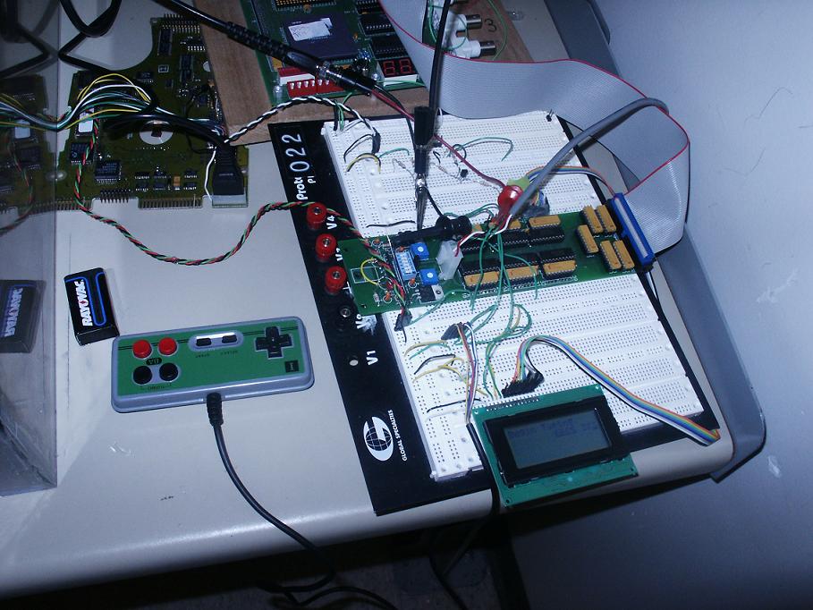
The MPC 823 processed the user input from a game pad and displayed information on a LCD panel. It sends the user input to the MPC 555 via serial port with a laser and a light sensor in between the two serial ports. This was required because we could not have a wire connecting the spinning display and the outside world. The MPC 823 FPGA had all of the hardware needed for interfacing to user I/O.
Team Member Tasks
Andrew worked on the user control. He worked on the LCD panel and the game pad controller. He worked on the programming for the MPC 823. Chris worked on the display wheel, including motor control and programmed the MPC 555.
Hardware Design
We programmed the MPC 823 FPGA to make hardware to control the LCD, motor, and game pad. The LCD hardware used counters to allow for the setup and hold times of the LCD. The eight pins on the Expansion Board that were set up for input and output were used for the data bus lines to the LCD. The DIR pin on the Expansion Board was used to control the settings for the eight pins. We chose to implement a bidirectional link to the character display so we could check the busy state of the screen controller to know that it was safe to write the next character.
The game pad controller used a counter to send clock pulses to the game pad and a shift register to receive the data. When a button press occurred, the counters would halt and an interrupt would be thrown until the value could be read out.
The PWM controller was just a simple counter in hardware that counted at a fixed rate, and at some programmable value it would switch the output from low to high.
The sensor we used was tied directly to an interrupt line on the MPC823 and every time the LED stick passed over the sensor an interrupt was triggered. Processor timers were used to calculate the speed of the motor by measuring the time between interrupts.
The hardware for the MPC555 was much simpler, and consisted of an identical sensor attached directly to one of the General Purpose Input pins on the board, and 12 LEDs attached to General Purpose Outputs.
Both processors also needed a chip to convert the RS232 level signal to something we could modulate through our laser, and then boost it back up to RS232 levels
Software Design
For the MPC 823, we used external interrupts for the game pad and the sensor. We used a processor internal timer for the speed calculation because that was the only timer we needed on the MPC 823 end. Since LCD initialization was a one-time event, we used busy loops to wait for each stage to complete until the busy flag was available to be read. We wrote some assembly drivers for the LCD, motor and game pad. We also used assembly to initialize the system and write the basics of our ISR. We used C code to do all the rest of the major work like calculating motor speed and controlling the LCD with the game pad. We wrote a finite state machine that controlled the LCD with inputs from the game pad triggering state transitions.
The software on the MPC555 consisted of two timers, one to measure the time it took for a full revolution of the wheel, and a second to trigger each individual pixel transition based on wheel speed. We encountered some difficulties getting the 555 to flash reliably, which is required for interrupts, so we just use a 'round robin' polling strategy for our sensor, timers, and the serial link. The main image buffer was a large array, big enough for 360x12 pixels across 30 consecutive frames of video. Our text functions didn't output to the display directly, rather they rendered the text into the image buffer, allowing for a more predictable timing behavior.

Results of the Design
Our design worked well in the end. The motor spun properly, images were displayed very clearly, and all the components worked. We did not have time to implement image uploading from the 823 to the 555, so we only had text mode enabled by the end of the project. Because of the use of polling rather than interrupts for the 555 timings, the display was prone to glitching whenever a character was sent across, because the entire text being displayed needed to be re-rendered. The time it took to do this processing exceeded the time between pixel updates, causing the entire display to shift a few pixels to the left for a single revolution. On the 823, we had a few issues with glitches in the revolution sensor and the gamepad buttons either bouncing or providing incorrect readings, so for the motor controller we implemented a running average to help dampen the effects of these incorrect readings. For the gamepad, we simply made it so only one reading could be taken per revolution of the wheel.
Conclusions
The components we used for the final version of the project all worked together and made the POV Writer work on a very reliable basis. Given what we know now, we would have spent less time fine-tuning the motor control at the beginning. With all the changed we made to the weight and balance of the Display Wheel, we had to adjust the motor control many times. We should have left it in a more basic state until the end. We would also spend more time making images, possibly even animations a few frames long to display on the Display Wheel.