|
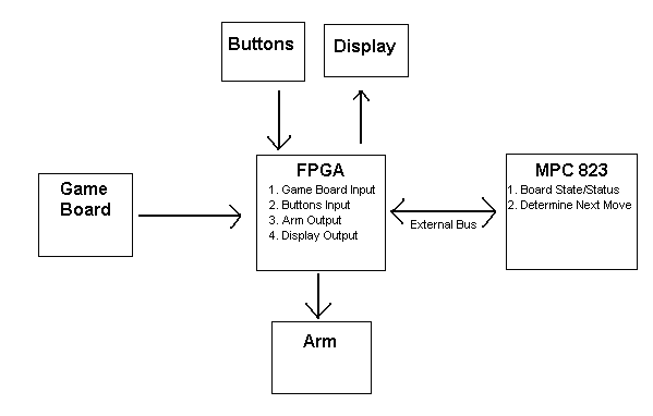 Figure 1: Overview of High Level Design
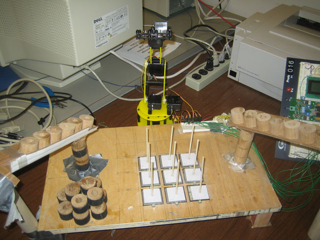
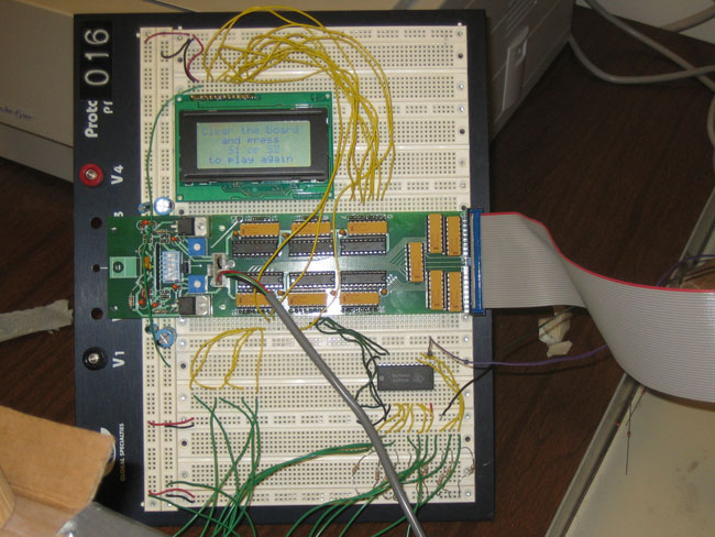
Generating these control signals required a counter for the 20 ms period, along with a register and comparator for each of the five servos to determine the pulse width. Writing a value to one of the specified memory locations would cause that particular output signal to remain high until the counter reached the written value at which point the output would go to a low state. The signal would then remain in that state until the counter reached 20ms, when it would be reset and the output would return to a high state. Sensors: The force sensing resistors used to detect the human player's game piece placement decrease their resistance as greater force is applied. Thus the voltage across these resistors was used to determine whether or not an additional game piece had been added to one of the stacks. The nine different sensors were connected via an analog multiplexor to a single input into the analog to digital converter on the EECS 373 lab board, and the address lines to the mux were controlled by a write command to the appropriate memory address. The end of conversion signal from the ADC triggered a bit at a specified memory location to flip to one, notifying the polling software that the digital data could then be read. This bit could then be reset by writing a one to the same address. LCD: The LCD character display was controlled by 4 signals: register select, read/write, enable, and 8 data bits. The register select state was determined by the last bit of the address being written to. The read/write signal was tied low, as only writes were required to interface to the display. The timing of the enable signal had to meet the HD44780U controller specifications, which was accomplished by means of a series of flip-flops in hardware. Because the LCD controller would only read the data lines when an enable signal was received, the 8 data bits were driven at all times from the primary data bus. Buttons: Switches 1 and 2 were used in the design. Pressing one of the buttons would write a bit to a particular flip flop. These flip-flops could then be cleared by writing a one to a specified memory address.
Sensors: In order to check the value of one of the nine sensors, a write was used to start an analog to digital conversion. The data written selected the address used in the analog multiplexor. Following the start of a conversion, the software would poll to determine if an EOC signal had been generated by the ADC. Once the EOC was generated, the converted digital value was read. This code was written in assembly. At the beginning of each of the human's moves, the values on each of the nine sensors would be read in a total of 50 times to determine the maximum value. The software would then loop through and check to see if any sensor's value was greater than its previous maximum. Once a value was detected that was greater than the previous maximum, a slight pause would occur followed by another loop to double check and make sure a move actually occurred at that spot. This portion of the code was written in C. LCD: All of the code to control the LCD was written in assembly. The first function called initialized the display according to the specification. Following initialization, sequences of letter were written along with the locations that each line would start on. Each addition message we wrote would clear the display before writing to it. We had functions to display a welcome message, starting menu, who's turn it is, who won, and a play again message. Game Algorithm: The entire function to determine the computer's next move was coded in C. The input to the function was the current state of the board and a "randomly" generated number and the output was the updated board. To determine the "random" number, an ADC conversion was called on one of our sensors at the start of the game. The random number was the converted value % 4. The first thing the computer looked for in a move was if it could win in its next move. Secondly, it checked to see if the human could win and if so it blocked that move. The next thing the computer looked for was if it was a legal move to take the middle piece since this is the most valuable move in the game. If the first three conditions were not met, the random number would come into play. We created four separate routines which were aimed at taking corner pieces on the lowest level and block the human from winning on the lowest level. Once the lowest level was filled, the computer moved to any open spot. Overall Organization: When our program first starts, the LCD is initialized, the arm is moved to its reset position, and a power setting is changed to allow for accurate control of the arm. Next, the welcome menu is displayed followed by a pause and a prompt asking who will go first. Once the game starts a loop is used until one player wins. The LCD displays which player's turn it current is. Players rotate making moves and once the game ends either a victor or defeat message is displayed along with the arm either taunting or falling down in defeat. After a few seconds pass, the arm goes back to its reset position and a message is displayed saying to clear the board and press a button in order to play again.
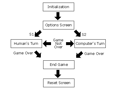 Figure 2: High Level Software Flow Chart
The case where the arm would pickup and drop a game piece in such a manner that it missed the stack can best be described as a control problem. Operating within the limited resolution of the servo motors and the fairly high degree of accuracy this game called for, the hardware and software were designed as well as they could have been regarding this problem. The issue was primarily a result of poor pick ups due to the imperfect nature of the delivery slide (re: it was made out of cardboard and duct tape). A better constructed pick-up location would most likely have prevented most of these misses. Regarding the force sensing resistors, both false positives (detecting a move when no piece was played) and misses of pieces actually played were encountered. The main issue was that the pieces themselves had a very low mass. Consequently the added weight of a new piece would sometimes have no effect on the voltage across the resistor. In order to counter this problem the threshold voltage at which a new piece is detected could be lowered, but this would increase the likelihood of false positives. Eliminating this problem entirely would either require more accurate sensors or constructing significantly heavier game pieces.
Click here to see a video of the game
Optrex 16433 Manufacturers Spec FSR Guide Servo Manual
|
|
|