RC Car Project
EECS373 - Fall 2007 - Final Project
Team Members and tasks performed:
- Andrew Turckes
- Designed Control Strategy
- Built hardware interfacing components
- Wired Car
- Neal Turett
- Configured Compiler Interface
- Wrote device drivers for internal and external components
High Level Design
The RC car is navigated through one of two modes. The first allows the RC car to drive in a straight line down the center of the hallway.
To achieve this, input is taken from ultra-sonic sensors mounted on either side of the car, returning the distance of the walls in
relation to the car. A PID feedback loop is then used to center the car in the middle of the hallway.
The second mode allows the car to follow an IR beacon. 5 IR transcievers are mounted on the front of the car. When a signal is
recieved on either side of the vehicle, it begins to turn in that direction. Once it has turned enough that the signal is now being
detected on the forward-facing IR transcievers, the car halts. When the IR signal is removed, it will re-enter wall-following mode.
The combination of these two modes allow the car to navigate straight hallways independently, and turn corners with the assistance
of an external IR source.
Hardware Design
Major hardware components:
- MPC555 - The MPC555 was used in favor of the MPC823 because the MPC555 is small enough to be mounted onto the car.
It does not have a FPGA, however, it does have a variety of sub-processors which were used for dedicated I/O tasks.
- Modular Input/Output System (MIOS) - The MIOS handles PWM output and pulse width measurement. The PWM outputs
are used to control the servo angle and drive motor speed, as well as to send the triggering pulse to the ultrasonic sensors.
The pulse width measurement function was implemented
to read the distance reported by the ultrasonic sensors.
- Queued Analog to Digial Converters (QADC64) - The QADC provides synchronous and asynchronous conversion of analog
voltages to digital values. This was used to read a value from the IR distance sensor.
- General Purpose Input/Output (GPIO) - The MPC555 has a series of pins which can be toggled between high and low states,
or be configured to read in a boolean value. These were used to interface with the IR transcievers.
- Ultrasonic Sensors - A Daventech SRF04 sensor
was mounted onto either side of the car to determine the distance between the car and the wall. Scans are triggered by a short
pulse driven from the MIOS. This results in a pulse of varying length dependent on distance, which is measured by the MIOS.
- Infrafred Distance Sensors - A Shart GP2D12
infrared distance sensor was mounted onto the front of the car to ensure that the car didn't drive into things. An analog voltage
is outputted to the ADC module on the processor.
- IR Remote Transcievers - IR remote transcievers were mounted onto the front of the car in different directions to allow
the car to detect an IR pulse and steer accordingly. Click here for the software implementation for this device.
Output is written to GPIO pins and detected in software.
- Motor Control - An IRFxxxx transistor was used to drive the motor based off a PWM signal from the MIOS.
- Servo - A servo was used to control the angle of the front wheels of the car, controlled by a PWM signal from the MIOS.
Software Components
- Device Drivers:
- MIOS Interface Code - The MIOS is fairly complex and has many registers
associated with it. Functions were implemented allowing easy access to each
of 8 PWM output channels and 10 pulse measurement channels.
- QADC Interface Code - The QADC can be operated in many different modes.
Functions were implemented which initiate a synchronous conversion on any
analog input channel then return the result.
- GPIO Interface Code - The GPIO supports banks of pins which can be configured
for input or output. GetPin and SetPin functions were implemented to allow
for easy access to any individual pin.
- IR Pulse Detection - See here for a discussion of
the IR transcievers and device driver.
- Control code:
- Ultrasonic distance sensing - The sensor data from the walls was first
run through two filters. The first eliminated any outlying data for a period
of time. This prevented any sudden changes that would adversely control
strategy. Then the values were put through a running average filter to smooth
out any smaller disturbances.
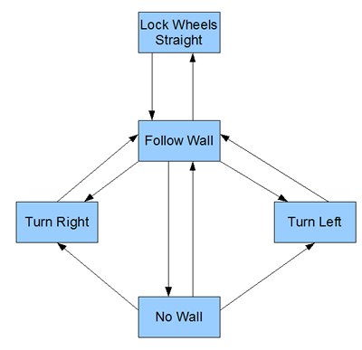
- IR controlled turning - The control strategy state machine are shown in
the diagrams below. The steering angle for wall following was done using
a PID controller based on a filtered version of the wall distance. The vehicle
was in a wall following mode while in the Follow Wall state. It could transition
into a lock wheels state which was used for testing. While in a wall following
mode the vehicle would continue until an IR signal was detected and would
make a turn into another hallway. Upon completion of the turn the vehicle
would resume wall following. When no wall was detected the vehicle would
continue straight until it turned or began to see a wall.
- Motor Control- The motor was controlled using a PWM signal and would apply
more torque when starting from a stop, then reduce the duty cycle after
a few seconds and the vehicle was moving. When IR was detected in the front
IR sensors and the car had not completed a turn the motor would stop and
stay stationary until the IR source was turned off.
- IR Tracking mode - When a pulse is detected on either side-mounted sensor,
the wheels turn in the direction of the recieved pulse. Once the car re-orients
itself so that the pulse is being recieved from the front sensors, the wheels
return to straight, wait a pre-determined amount of time, then stop the
motor.
Design Results
The major challange faced in regards to the control system was paramater calibration. We used a panel of dip switches
to tune values experimentally but that process was slow and we could only work with one parameter a time.
We also faced problems with EMF on the sensor lines due to interference
from the motor lines. We also had problems detecting
IR pulses without interrupts. The sensors demodulate a signal from a regular IR remote and pass out the data.
We had to detect that data was present and then use that to say that we need to make a turn in that direction.
The major impediment to solving most of the above problems was time. All in all, however, the project did work.
Conclusions
If we worked on the project again we would probably use more sensors to gain information about obstacles and the walls
to better control the cars steering ability. The final version was able to steer the car very well in a straight hallway
with out many juts in the wall. We were able to turn into another hall and center ourselves. We would also have implemented
interrupts and used the TPU co-processors to filter signals before they reached the MPC555.
See also: