Title
“Wii” (We) - Golf
Members
Jerald Chan
Edwin Lee
Introduction
Our overall project design is a “mini-golf” game in which the user controls the force applied to the ball in order to putt the ball into a virtual “hole”. We intend to control the force applied by using an accelerometer. The “club” used to putt the ball will be controlled by a heavy duty servo, which will generate the force to push the ball forward. An ultrasonic distance sensor will inform the player about how close he manages to putt the ball near the virtual hole, scoring more points the nearer the ball is to the hole. The player’s score will be updated on the LCD display. The distance of the ball starting position from the virtual hole will be able to be adjusted via the slide switches on the FPGA.
High Level
Design
Heavy Duty Servo
Function: To produce torque to putt the ball.
Measurements: It was necessary to determine the angles of rotation of the servo when it was fed with pulses of varying duty-cycles. Only with this information were we able to properly calibrate the servo to produce the amount of rotation that was necessary to play Wii Golf. We performed the measurements and calibration using pulses from the waveform generator.
Control Algorithm: After obtaining the aforementioned measurements, we had to write an algorithm in software to generate the appropriate pulses based on readings from the accelerometer. A larger reading will produce a pulse with a larger duty cycle.
Accelerometer
Function: Used as a Wii-mote. The player swings a real golf-club with the accelerometer attached on. The swing generates torque in the heavy duty servo.
Measurements: We had to measure the maximum voltage that the device can generate, as well as the voltage produced when the device is stationary. The analog voltage is converted into digital values by the ADC.
Control Algorithm: The converted readings from the ADC had to be translated into duty cycle for the servo.
The
following part of the design involves a measurement of the distance of the ball
from its starting position and outputting that distance calculated onto the LCD
display. This also involves the calculation of the actual distance of the ball
from the virtual distance that is set by the slide switches which is also
output on the LCD as points earned, out of a 100 maximum.
Ultrasonic sensor
Function:
To measure the distance of the ball from the starting position.
Control
Algorithm: The ultrasonic distance sensor is powered by an input pulse of at
least 10μs in length which emits an output pulse.
Measurements:
The measurement of the time it takes for the output pulse to be echoed back to
the sensor can be converted to actual distance of the object from itself. The
length of the output pulse was used to run a counter which resets on every
falling edge of this pulse. This count value is latched into a register which
can be read whenever we want to. This count value was used to as a calibration
of the distance of the ball.
LCD Display
Function:
The LCD display receives the converted distance value and the value of points
earned and displays them.
Control
Algorithm: We implemented the LCD using the efficient busy-bit read implementation
which basically flags us if we write to the LCD while there is an internal
operation going on. The LCD Enable signal latches the data into the LCD
Display.
High Level
Functional Block Diagram
Member Task
Distribution
List the tasks each member is
responsible for and performed.
Jerald—interfaced the LCD Display
and Ultrasonic sensor
Edwin—interfaced the Accelerometer
and Heavy Duty Servo
Both—interfaced both parts of the
design to complete the game
High Level Design
Hardware Design
Pulse generator
This component essentially consists of a decoder that we designed and a toggle flip-flop. By write to a particular memory location using software, the decoder will produce a signal to toggle the flip-flop’s output. The output is the PWM that we feed to the accelerometer.
ADC controls
The components are identical to those we designed in Lab 8. We designed a decoder to generate the ALE/START, OE, AD_WR signals for the ADC. The signals were passed through a series of cascaded D flip-flops to ensure that the pulse lengths meet the minimum requirements of the ADC0808 specifications. The EOC signal generates an IRQ1 interrupt.
Generation
of input pulse for ultrasonic sensor
We
divided the 10MHz bus clock using cascaded 16-bit and 8-bit counters to provide
the pulse we needed. We needed a 20 Hz clock. We chose to implement the
generation of this pulse in hardware mainly because it was straightforward.
Generation
of distance count value
We
used a counter with the output pulse of the sensor as an enable with the
divided clock. The count is latched into an output register on every falling
edge of the output pulse.
Reading a
consistent distance count value
Control
Algorithm: We provided a read data-path to read the distance output register by
generating the standard TA* signals, decoding the right address (we used
0x03100000) and enabling the right tri-state buffers.
Reading
from the LCD – for the busy bit
To read from the LCD we wrote to
address 0x03000000, and generated our required signals via our address decoder.
The busy-bit provided in the LCD
Display was read to find out if we are able to write to the LCD Display. We had
to wait for the busy bit to deassert itself before we were able to proceed with
writing. We did not use the timer alternative to anticipate the latency time
between writes, which was more inelegant than the busy-bit implementation that
we chose.
To do this, we had to make bits 0-7
on the expansion board independent of the bi-directional drivers by utilizing
the DIR bit—generated when the correct address was decoded with TS*.
Writing
to the LCD
To
write to the LCD we wrote to address 0x03000000 as well and differentiated a
write from a read by also decoding the provided RD_WR_BAR. The required LCD signals
were generated with each write, the LCD display latching the value to be
written on the falling edge of the LCD’s enable signal. We wrote the ASCII code
of the characters we wanted displayed.
Software
Design
Reading a consistent
distance count value and converting this count into points.
We
read from 0x03100000 to obtain the distance count.
We
also read from 0x02900000 (the slide switches) to obtain the distance of the
virtual hole. With the distance and the count, we took the absolute difference
and subtracted that from a total of 100 points. With this information, we
proceeded to write the distance and the points earned to the LCD via the LCD’s
write datapath.
Reading
from the LCD – for the busy bit
We read from 0x03000000 as provided
by the hardware to check for the busy bit.
Writing
to the LCD
We had to wait for the deassertion
of the LCD’s busy flag before we could write to it. We thus implemented and
provided the read datapath from the processor to the LCD to do this. We spun
the software in a loop until this busy flag was deasserted before we proceeded
with writing the required information. Drivers had to be written for the
writing of characters to the LCD display.
Generating
an interrupt every 1 second to update LCD Display
We
used the System’s Real-Time Clock (RTCSC) to generate a LVL0 interrupt every 1
second. To calculate the point values, we branch to a C function with the
distance count value and the slide switches value as input arguments. After the
return from C code to assembly, we proceeded to write both the points value and
distance value to the LCD display.
Pulse Generation
Interrupt (Assembly)
We used the first general purpose timer to generate a 50 Hz pulse for the servo. We used the software timer because we had to vary the duty cycle based on the ADC values; using software makes it much more intuitive to design. The timer generates two interrupts over every period of the pulse: one interrupt sets the pulse high while the other toggles the pulse low.
Write ADC Value
Interrupt (Assembly)
We used the second general purpose timer to generate control signals to write to the ADC at 500 Hz.
Read ADC Value
Interrupt (Assembly)
This interrupt is triggered in hardware by the EOC signal. The code checks if the ADC value is above 3V, which is the threshold we set for generating torque on the servo. If the value is above 3V, 500 values including the first that exceeds the threshold will be stored into memory. Flags are used in this part of the code to control when to store the values.
Set/Reset Duty
Cycle (C)
The largest value among the 500 stored in memory is used to determine duty-cycle. A linear scale was used: 3V generates a duty cycle of 3%, while 4.8V produces a duty cycle of 12%. The duty cycle is reset to 1% 4 seconds after a new PWM is generated.
Results of
the Design
Initially the accelerometer generated a maximum output voltage of 2.8V and a stationary voltage of 2V. This gave us only 0.8V to work with, which meant that the sensitivity of the accelerometer is compromised. We had to pass the output through a series of electrical components to amplify the voltage to a range of 3V-5V, thus giving us 2V to calibrate the servo with.
Conclusions
The final product of our project was exactly what we set out to achieve from the beginning.
Media
Provide photos of your project. You
should include views that best demonstrate
your final project. You may also
submit short MPEGs showing your project in action.
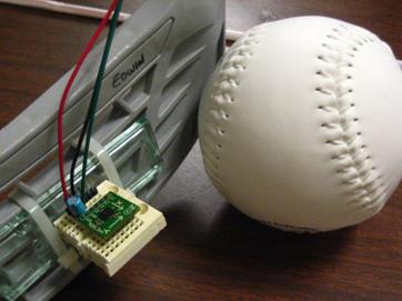
Accelerometer:
mounted on hockey stick (simulating golf club)
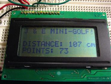
LCD
Display: Distance of the ball from its starting putt position and Points Earned
displayed.
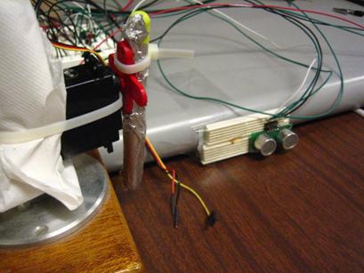
Ultrasonic
sensor and mounted Heavy Duty Servo: both at starting putt position.
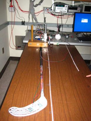
Overall
View of “Wii” (We) Golf
Video Clip
·
http://www.youtube.com/watch?v=aY1Wh_Ae2u0
References
Ultrasonic
Sensor:
·
http://www.eecs.umich.edu/courses/eecs373/Labs/devices/SRF04.pdf
·
http://www.eecs.umich.edu/courses/eecs373/Labs/devices/Devantech_Range_Finder_Yellow.pdf
LCD:
·
http://www.eecs.umich.edu/courses/eecs373/Labs/devices/optrex%20maufacturers%20spec.pdf
·
http://www.eecs.umich.edu/courses/eecs373/Labs/devices/hd44780u%20controller%20spec.pdf
·
http://www.eecs.umich.edu/courses/eecs373/Labs/devices/16433aae%20optrex%20specific%20spec.pdf
·
http://home.iae.nl/users/pouweha/lcd/lcd.shtml
Accelerometer:
·
http://www.sparkfun.com/commerce/product_info.php?products_id=692