Thrii Seventy Thrii Mote
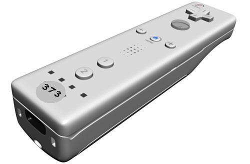
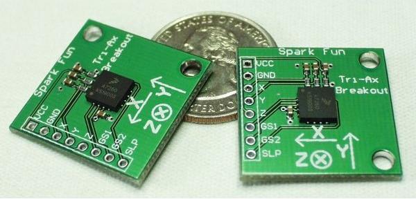
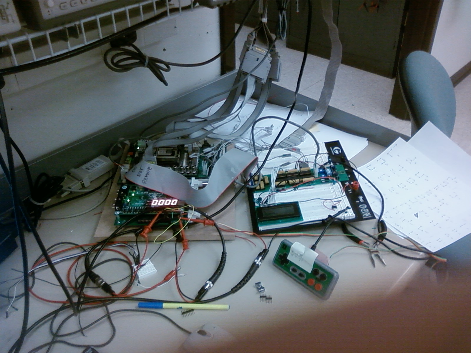
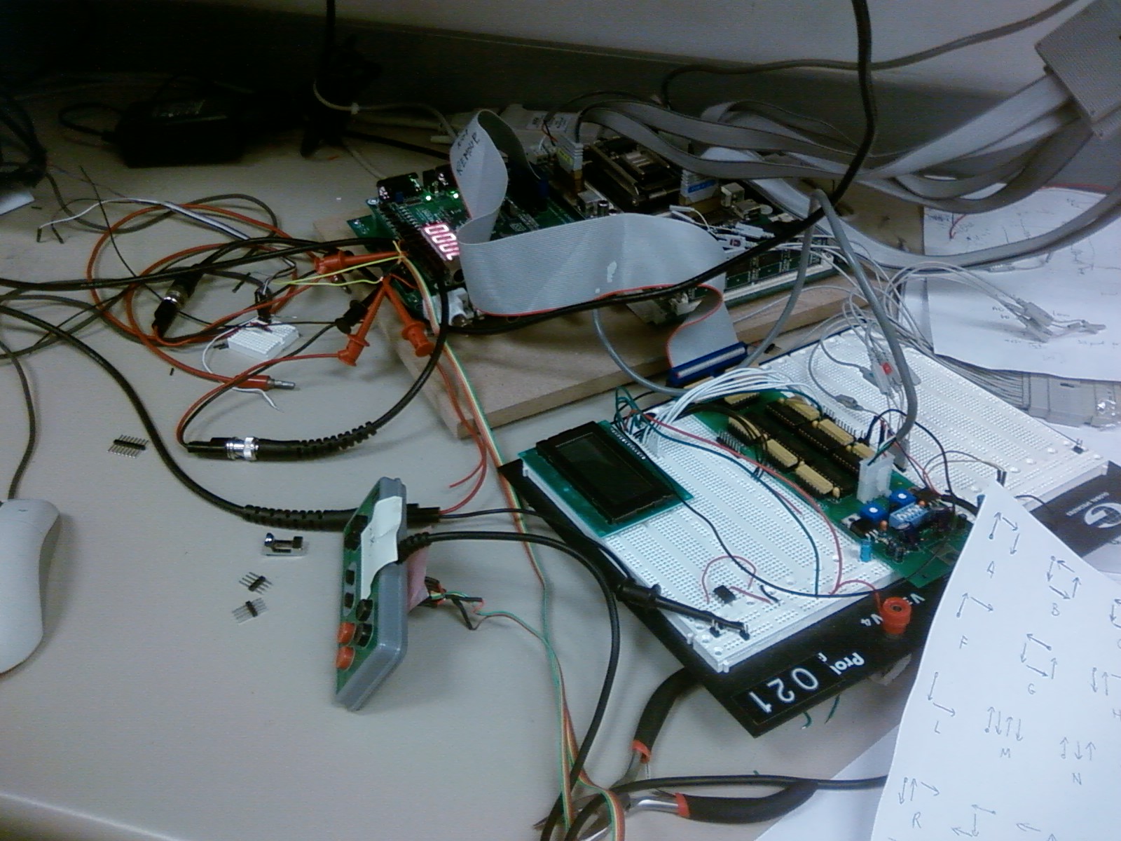
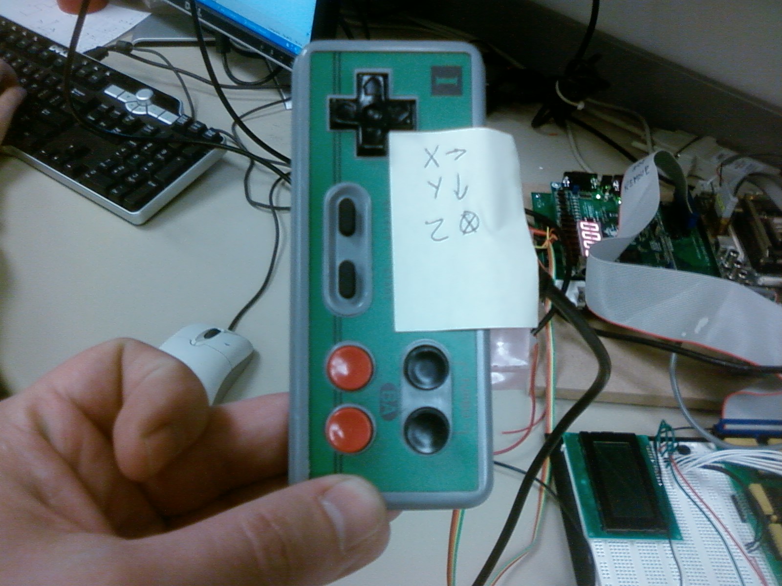
For this project, we created a device that would act similarly to a Wiimote. Our device integrates with a character display to allow a user to write on the display by making motions with the device in the air. The user can write letters, numbers, and some symbols on the character display by making vertical and horizontal motions with the remote. Our device consists of a three-axis accelerometer mounted to a Nintendo 8 controller.
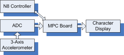
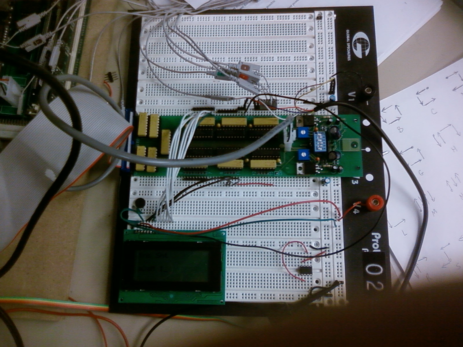
Our device consisted of a three-axis accelerometer mounted to a Nintendo 8 controller. The pins of the accelerometer were attached to three ports of the ADC. This allowed us to poll the ADC during an interrupt and save the values to global variables for use in our main C function. The buttons of the N8 controller replaced the buttons on the station kit to give the user a more genuine Wiimote experience. The C function polled the N8 controller for button presses and used the information to control what appeared on the character display. If information was obtained from the accelerometer while the A button was pressed, the software would draw a letter on the display. If the B button was pressed during the motion, the software would draw a number on the display. The other buttons on the remote had various status functions, for example shifting or insert vs. delete.
Ankit:
We created a clock divider to fulfill timing constraints for the devices. We needed modules to interface to the character display, the Nintendo 8 controller and the analog-to-digital converters. We wrote the display module and the ADC module in Verilog. The modules provided signals that met timing specifications and the required data signals for the devices.
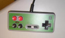
For the Nintendo 8 controller, we provided latch and pulse signals using the clock divider and used flip flops and a shift register to distinguish the buttons in the received data signal.
For the character display, we had to create and correctly time the signals we sent. Our hardware used the signals and timing specifications generated by the FPGA to provide the correct delay for the signals that we sent to the device.
The three pins of the accelerometer that correspond to the x, y, and z axes respectively were attached to ports 2, 3, 4 respectively. For the ADC, we had to create and correctly time the signals we sent. The ADC runs much more slowly than the bus clock, so we needed to provide the correct setup times, hold times, and delay between signals.
Before we started coding we had to decide exactly what responsibilities would be given to the hardware and then what would be done in assembly versus C. Initially, we thought we might need to make the bus between the PPC and the character display bi-directional, then we realized that bus time wasn't an issue and we didn't have to squeeze a lot of functionality in between display writes. At that point we were free to run the entire program in a discrete series of steps. This meant we would not need many interrupts since we can poll for I/O.
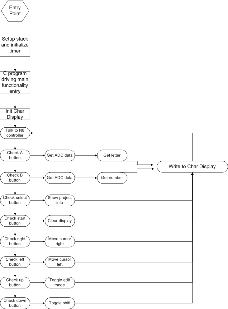
To gather data from the ADC we decided on a 500Hz sample rate. (It worked for lab 8 and if it ain't broke don't fix it.) To do this we setup one timer that would interrupt every 2ms. Acting as the main entry point for the application, setting up the timer and the interrupt and then calling the C function was all our assembly program was used for. Global variables were setup here for use in the C code. Variables "accelX" and "accelZ" were used to hold movement data from the accelerometers after the data was converted to digital by the ADC. The variable "count" was written to by the timer during each interrupt. This variable was used in the C code to give enough of a delay between write operations to the character display.
Most of the functionality was performed by the C function. Only one interrupt was needed and the C code sequentially polls all of the different parts of the Nintendo 8 controller.
Controller functionality (buttons):
A — create a character
B — create a number
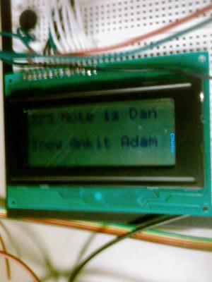
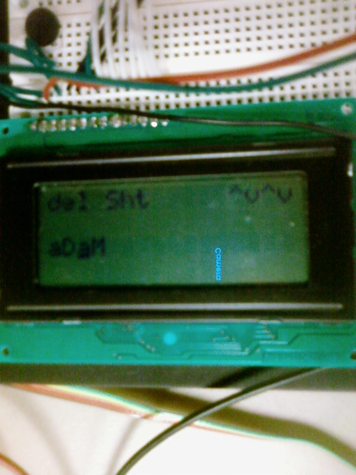
Select — display the project name and the names of the group members
Start — clear the display
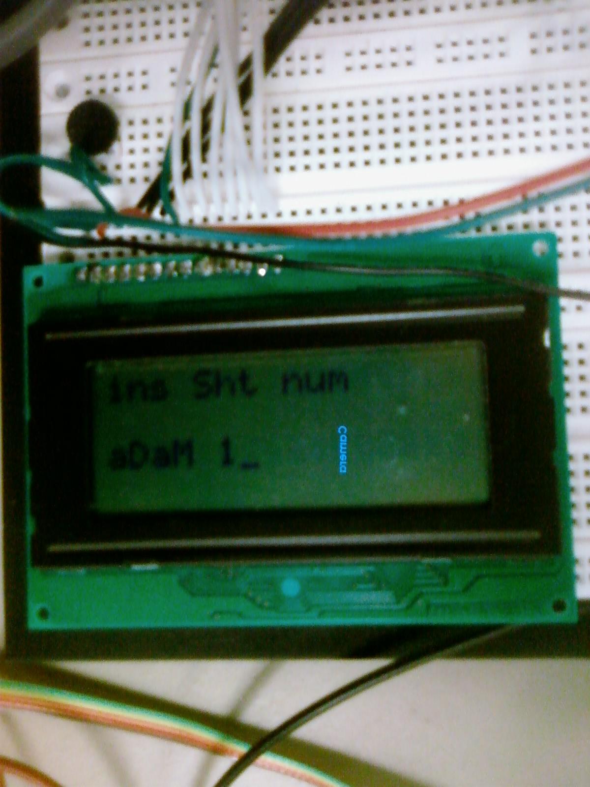
Up — toggle between "insert" and "overwrite" editing modes
Down — toggle between "shift" and none (to create capital letters)
Left — move the cursor left one space
Right — move the cursor right one space
If the A or B button is held and motions are made, the code will get data from the ADC via the two global variables and attempt to interpret the data as a character or number, respectively. Certain motions can also be made to edit the display. (See appendix for character map)
Once the controller has been polled and any writes have been made to the display, the code will start over by polling the Nintendo 8 controller again, ad infinitum.
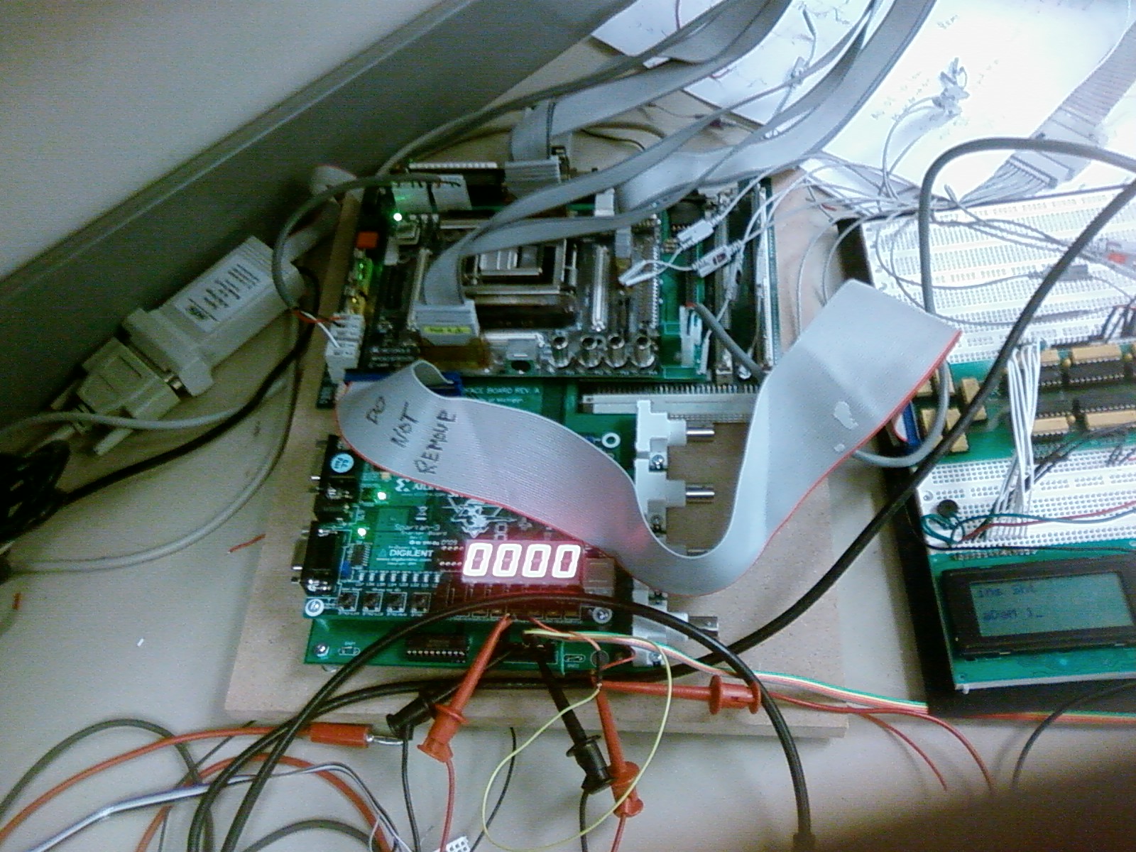
The character display came with a few stock bits of functionality. It could move the cursor, change the way the cursor looked and overwrite characters that were already being displayed. By adding an array to our code we were able to hold an exact duplicate of the display so that we can now implement a backspace, delete, and insert functionality.
Several timing issues became important very early in our design. The first version of our software was very simple and initialized the display, allowed the writing of characters and little else. This is when we discovered that we needed to add delays after writing to character display. A couple commands required 15.2ms but most only required 40us. Since we do not have a lot going on at once, we used the "count" variable to provide our delay at a resolution of 2ms. Once this was implemented we were able to successfully initialize the display. Soon after, we realized that a pause was needed after each write that displayed a character. After rewriting the software to add the additional functionality, the delays became slightly more complicated, and after a few "Software Emulation Exceptions" we realized that we needed to add a pause following each top level iteration.
The "gather data from the ADC" function was another source of timing issues. At the end of every motion made, there is a counter motion in the opposite direction. If left unprocessed, the raw ADC data will result in a second motion in the opposite direction being made. This makes it nearly impossible to implement any of our functionality. At first, we tried, unsuccessfully, to filter out all signals above our trigger threshold after a proper signal is decoded. This was supposed to get rid of the counter pulse. However well intentioned, it didn't work. Our next idea was the most successful, and now rarely results in a second, non-deliberate, motion to be detected. The software ignores output from the ADC for a few hundred milliseconds. This setting can be adjusted by changing code, if the sensitivity needs to be tweaked. We thought about adding the ability to change this during run time but it was a low priority function that missed the cut due to time constraints.
Another big challenge was the indication of false positives. When a person initiates a motion in a given direction, there is a small chance they will have a small spike of motion in a direction that is somewhat perpendicular to the intended direction. This spike may be shorter in duration but since it occurs first, it will cause a false positive in that direction. One idea was proposed to try to deal with this problem. A running total could be recorded by storing sampling of data instead of just the first value that exceeds the threshold. This would allow the software to use the greatest total for determination of direction instead of just the initial spike of motion. Time constraints and the relative low occurrence of false positives prevented this option from being explored.
Our design worked as expected when all was said and done. During the implementation, we had a few software issues and hardware issues with interfacing. When we were communicating with the character display in software, we found that we needed to add delay after each instruction sent to avoid a software emulation exception. In hardware, we had to change how we were latching the responses from the N8 controller because when we initially designed the latching, the values were not being latched correctly. The main reason for this was that we were latching on the wrong signal. We did not have to compromise functionality because of a sensor or actuator constraint, but we did remove our dimmer functionality because of time constraints. We needed to add a function to the C function to convert the values returned by the accelerometer to recognizable motions so the function could map the motions to characters. There were no unresolved problems with our design.
It was possible to implement our design with our components, but with more time we could have given the user a more genuine experience as well as added more functionality to the character display. For instance, we could have added functionality so that when the user drew an equals sign, the software would evaluate the preceding expression and output a numerical answer, similar to a calculator. We did not need more processing power for our design. If we had to do the project again, we probably would have started earlier to add more functionality. We may have added an infrared camera similar to the actual Wiimote to allow for position calculation. We also could have found a use for the third axis of our accelerometer. Starting earlier would also allow us to manage our time and delegate tasks more efficiently.

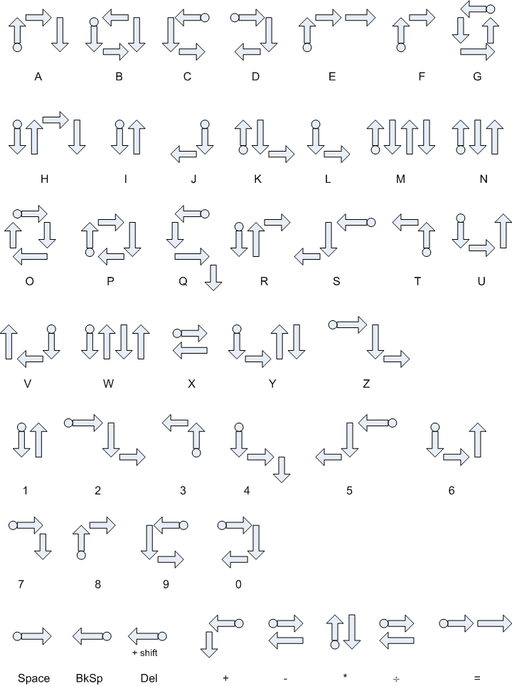 Motion Chart (click for high res version)