Members | Introduction | High Level Design | Hardware | Software | Results | Conclusions | Media | Reference
Quintin Evans
Shinan Li
Everyone
probably has played some Remote Controlled toy when he/she is a kid. What can
you do when you add an embedded processor to your RC? Our project transforms a
Remote Controlled Blimp into a self-navigated robot. It detects the sound
target at a specified frequency and travels toward it. Even though the task
looks simple, it gives you a good insight and valuable experience in
integrating the microprocessor to electronic systems.
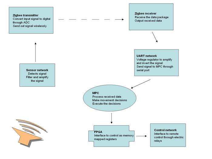
In
general, the sensor network on the blimp detects the noisy target. The sensor
network consists of condensed microphones and IR distance sensor. Microphones
detect the intensity of the target sound to determine the distance between the
blimp and the target and the direction of the target respected to the blimp. IR
sensor measures the distance between blimp and the obstacles in front of it to
prevent the blimp from running into it. The measurement results from the sensor
network are analog voltages. In order to transmit and process the data, we have
to convert the analog signal to digital signal through the ADC in Zigbee transmitter. After conversion, Zigbee
transmitter sends the data back to the ground wirelessly. The Zigbee Receiver receives the data and transfers it to the
MPC through a serial port. MPC processes the receiving data and determines what
the blimp is supposed to do. It sends control signals to the control network on
the FPGA expansion board. The control network amplifies the output signal from
the MPC and maps the signals to the remote control through electric relays. The
blimp will fly toward the target. When some obstacles come into the blimp��s
way, it will avoid it by rotate its position and fly around it.
|
Name |
Tasks |
|
Quintin Evans |
Sensor
network, control software, control network |
|
Shinan Li |
Zigbee software, UART |
Condensor Microphone-
o Behaves like a variable resistor. Sound waves cause the mic to vary in resistance which produces an analog voltage signal.
o A voltage divider consisting of the mic and a 2.2K resistor produced a voltage which was amplified by an op amp
o The microphone could pick up a 400mVpp sine wave that was over 30 feet away in the other part of the lab. Basically, if you could hear it, the microphone also could hear it.
o The microphone at most produced a 50mVpp waveform when the sound source was directly over the mic.
o It could pick up sound from all directions.
o A larger signal indicated that the sound source was closer.
Analog Bandpass Filter-
o Bandwidth of 80HZ which ranged from 200HZ to 280HZ with 240HZ being the most emphasized frequency.
o Limited the range of the overall microphone circuit to 20-25ft. We couldn��t get a signal from a sound source that was over 25 ft away.
o The output connected into the ADC of the Zigbee target board.
IR Distance Sensors-
o It measures distance by shining an infrared light and measuring the intensity of the reflected light.
o Works best on large targets with very reflective surfaces such as a tile floors or large sheets of white paper.
o Data is an analog voltage that ranges from 2V to 50mv.
o The distance range was from 1�� to ~35��
o Output voltage started at 1V when an object was 1�� away and peaked to 2V when ~5�� away and then decreased as object moved further away. At ~35�� away, data was unreliable.
o Data was connected to the ADC of the Zigbee Target Board.
Memory Mapped
Registers-
o When a 1 was written to a register, it completed a connection on the RC board of the blimp turning on 1 of three fans and causing the particular fan to spin either clockwise or counterclockwise.
o Output controlled relays.
Sensor Network-
o The condenser microphones, IR sensors, and analog filters comprised the sensor network.
o The network was on board the blimp and was powered by 2 lithium ion batteries.
Zigbee transmitter:
- The transmitter operates at
2.4 GHz for wireless transmission. The supply voltage of the transmitter
is 2 �C 3.6 V.
- It has five general purpose
I/O pins. We use four of them in our project.
- The pins connected to
microphones (A2, A3) convert the input analog signal (0 �C 2.5 V) to a 10
bit digital value (0 �C 1023). The 10bit result is zero extended to 16 bit
integer.
- The pins connected to IR
distance sensors (A12, A13) convert the input analog signal (-2.2 �C 1.8 V)
to a 10 bit digital value (0 �C 1023). The 10 bit result is zero extended
to 16 bit integer. Since the IR sensor only output positive voltage, so
the actual range of possible values are roughly 511-1023.
- The ADC converter is clocked
at about 5 MHz. It takes around 80 cycles to finish conversion. So
ideally, we get 62.5K conversions in a second at most.
- The transmitter could send up
to 200 Kbps, which is around 25 kilobytes per second.
Zigbee Receiver:
- The receiver also operates at
2.4 GHz for wireless transmission. The supply voltage is 2 �C 3.6 V.
- After receiving the data, the
receiver output it through the TX pin at a baud rate of 9600.
- The output pattern is started
with a 0 bit and ended with a 1 bit.
- The voltage regulating
network convert 0 - 3 V output from the Zigbee
receiver to -12 �C 12 V signals. (The signal is inverted in this process.)
- The output signal from
voltage regulating network is then connected to pin 3 (TX) of the male
serial port plug. GND is connected to pin 5.
- Serial port plug is connected
to MPC directly.
The
software used the real time clock��s 1 second interrupt. That second interrupt was used to
control the movement of the blimp.
There were several global movement functions: SPinRight,
SpinLeft, Up, Down, and Forward. There was also a global variable called
move. After a movement, a
data packet from the wireless ADC was read. The values sent wirelessly were the
voltages of the various sensors in our sensor network. Based on those values of the sensors, a
movement function was called. It
would take time for the fans to move the blimp and its respective load, so we
used the RTC second interrupt to increment a global variable. Each movement function would wait until
the global variable reached a value and then turned off all fans used. This allowed us to have better control
of the movements of the blimp. We
could set a fan to run for 5 seconds and the fan would actually run 5 seconds
+/- 1 second. We used the real time
clock because we were familiar with the 1 second timer, it was accurate and it
saved us the effort of making our own.
The global movement functions, initialization function, and interrupts
were written in assembly. The
control code was written in C to simplify the decision making process.
The
software in Zigbee receiver is unchanged from the
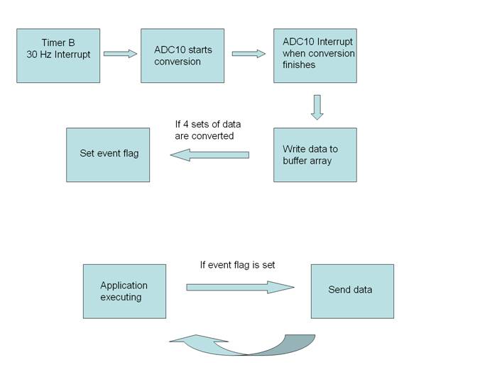
sample application. The code in Zigbee transmitter is
modified. The transmitter is set to read the analog signal in each of the four
I/O pins we used and convert the result to digital signal through ADC. This
conversion is triggered by Timer B interrupt. Timer B is configured respect to
Timer A, which is clocked at 1.5 KHz. In our program, we scaled Timer B further
down to 30 Hz. It means that the transmitter start conversion at a frequency of
30 Hz. After the conversion is done, ADC 10 triggers its event interrupt which
puts the result in a global array. When all four ports have been read, halEventFlags is set by the ADC 10 interrupt. When the
running program appExecHal in transmitter detects the
halEventFlags, it calls appSrceData
function and send out the data.
There
were numerous problems that occurred with this project. First of all, we ordered special op amps
that could operate with one supply rail grounded so that our battery pack for
the sensor network could be smaller.
The op-amps didn��t work well with a single supply rail, so we had to
increase the battery pack so that the op-amps could have dual supply rails and
operate properly for filtering and amplification. Also, the sensor network was too heavy
for the blimp to lift. For ease of
assembly, the analog filter had been assembled on a cutup breadboard. This proved to be too heavy so we had to
solder the 2 analog filters using small solder boards to lessen the load. The blimp was able to lift this newly
fashioned sensor network. Also, to
interface with the RC controller, it turned out that metal contacts were
pressed which told a fan which direction to spin. We tried to use a transistor (both
MOSFET and BJT) as a switch between the contacts and apply a ��1�� to the gate of
the transistor to turn the fan on and a ��0�� to turn the fan off. This did not work. As soon as a physical connection was
made between the contacts (even using a dead transistor), the fans spun
continuously. We had to use
electrical relays that completed the physical connection between the two
contacts when a ��1�� was applied and opened the connection when a ��0�� was
applied. Also, there were problems
with the ZigBee device that we used. We had to get a crash course in the ZigBee device from Dr. Metger,
Sean Whipple, and Hari who were using the device in
the 452 class. The code that we
wrote for the board initially didn��t work.
We kept trying, but it wouldn��t work correctly. It turned out that the board we were
using was buggy and when we switched to a new board, our code worked
correctly. Last, the RC board
controlling the blimp fans burned out.
We could not get another board in enough time to finish our
project.
The
project that we selected was too big for the amount of people we had in our
group and the time given us.
Our control loop could have worked, but it is a very difficult loop to
configure. We got every component
in the loop to work correctly, but we had to do much fine tuning to get the
entire system to work together. It
can work, but there were a lot of problems that tripped us up and made it
impossible for us to finish in the time allotted. In the end, the sensor network worked,
we could control the blimps movements, and we could relay data wirelessly. Unfortunately, our RC board burned out
and we couldn��t demonstrate a working feedback loop.
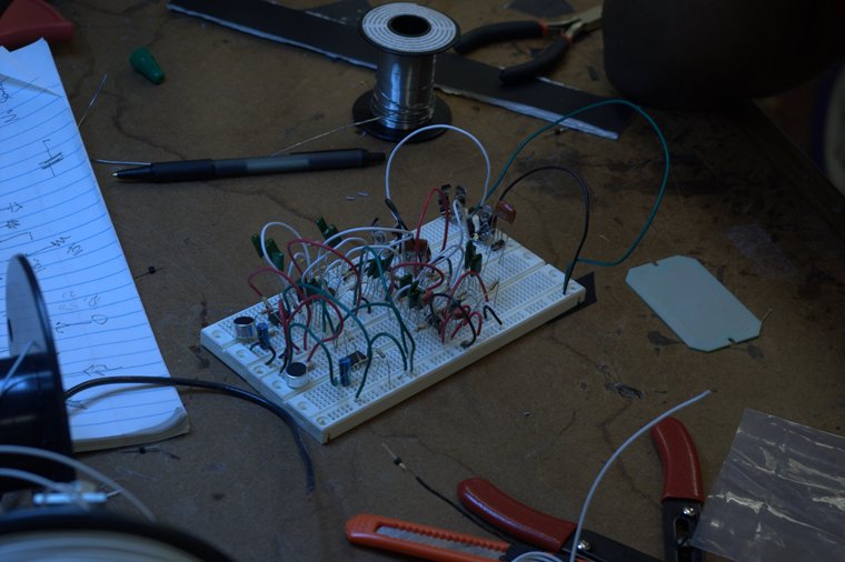
Figure 1 Sensor Network
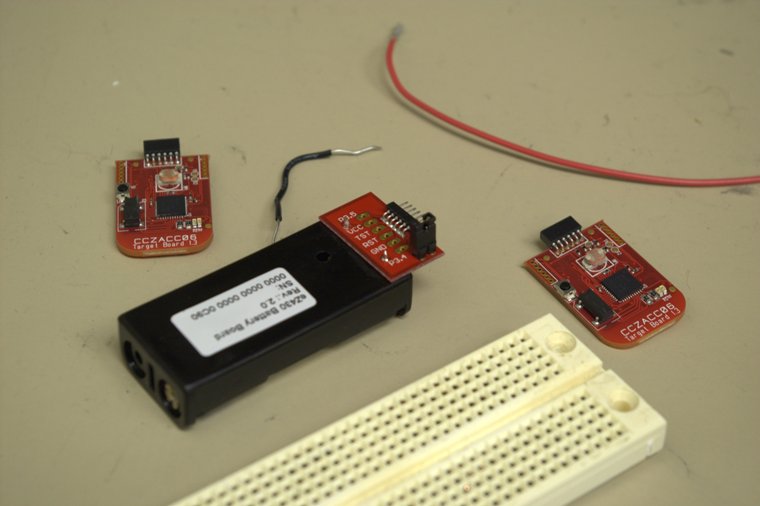
Figure 2 Zigbee transmitter, receiver and battery case
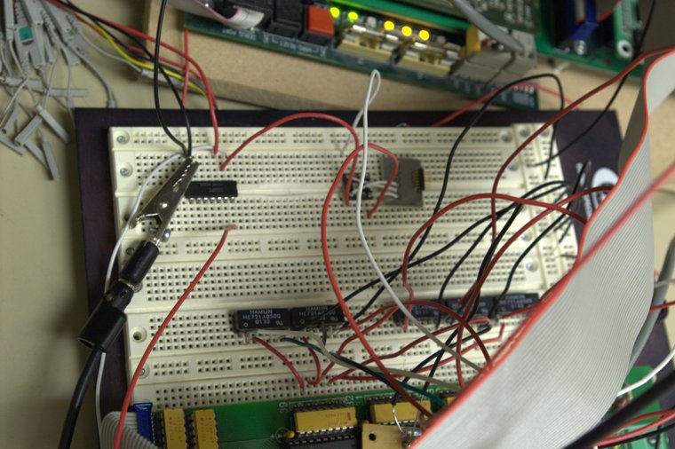
Figure 3 Zigbee UART network and control network
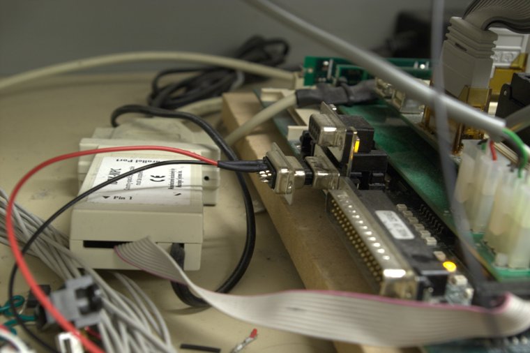
Figure 4 interface to serial port on MPC
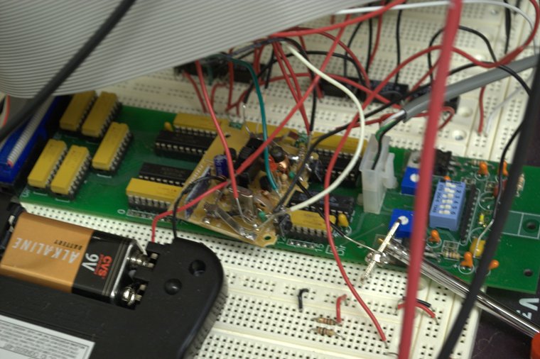
Figure 5 interface remote control
Mach IIIz RC 3 channel Blimp
http://www.rctoys.com/rc-products/MACH-3Z.html
Z-Accel Demonstration Kit
http://focus.ti.com/docs/toolsw/folders/print/ez430-rf2480.html