AutoPen
AutoPen
Abbey Heinlein and Amy Liebowitz
EECS 373 Winter '05
Description
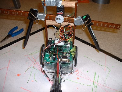
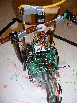
AutoPen is a car with markers attached on top controlled by an 8-bit Nintendo controller. The arrow buttons make the car go forward, backward, and turn, while the A and B buttons raise and lower the right and left marker, respectively. The select button activates (and deactivates) an orthogonal mode that only allows the car to turn at right angles. AutoPen is also equipped with an optical sensor on the front distinguishes between white paper and black electrical tape. When used on a large sheet of white paper held down by black tape, AutoPen turns 180 degrees whenever it reaches the edge of the paper, preventing the user from drawing off the paper and marking up the floor.
Components
- Nintendo 8 controller: The controller input was handled with a combination of polling and an interrupt connected to IRQ7. The data returned from the controller at a rate of 60 Hz was continuously polled and compared to the data from the previous cycle. When the data changed between cycles, an interrupt was generated to process the new data and send the correct control information to the AutoPen servos.
- Left & right wheel servos (modified for continuous rotation): The output to the wheel servos was implemented with counters to create a variable-length pulse every 20 ms. The length of the pulse was determined in software depending on the desired action for the servo (forward, backward, or stop).
- Pen lever servo: The pen servo output was generated in a similar manner as the wheel servos, but with a high pulse every 13.1 ms. The length of the pulse was controlled by software depending on the state of the pens (left pen, right pen, off).
- Optical sensor: The optical sensor input was handled as in interrupt on IRQ7, after being processed through a short counter to eliminate glitches.
Difficulties
Our first difficulty was in generating the latch and pulse signals to send to the Nintendo controller, and in reading in the serial data returned from the controller. We eventually used counters to generate a 12 us high latch signal followed 6 us later by 8 high pulses (6 us high, 6 us low) on the pulse signal, and the Xilinx serial to parallel macro to read the returned data. Also after about two weeks of trying to get the generic controllers found in the lab to function properly, we switched to Amy’s own original Nintendo controllers from home, which gave much better results.
The next difficulty we encountered was getting the pen servo to rotate the correct amounts. Fixing this was basically a matter of trial and error with different frequencies of signal pulses.
We also had trouble with the optical sensor getting glitches and triggering the sensor interrupt when it hadn't actually encountered the black tape. We dealt with this by inserting a counter between the sensor data and the interrupt input of the PROC macro, so the signal had to stay changed for a certain amount of time before it would register as an interrupt.
Our final difficulty was in trying to add a second optical sensor to the back of the AutoPen. We realized that our handler routine (turning 180 degrees) wouldn't be a reasonable way to deal the AutoPen backing over the tape. We realized this too late to change it, but would have liked to add hardware to read from the data bus which sensor was being activated and software to handle each of the sensor interrupts differently.
![]()
(If video doesn't appear above, click here)
Click here for another video of AutoPen in action