Home Security System
By Andrew Huah, Victor Chan
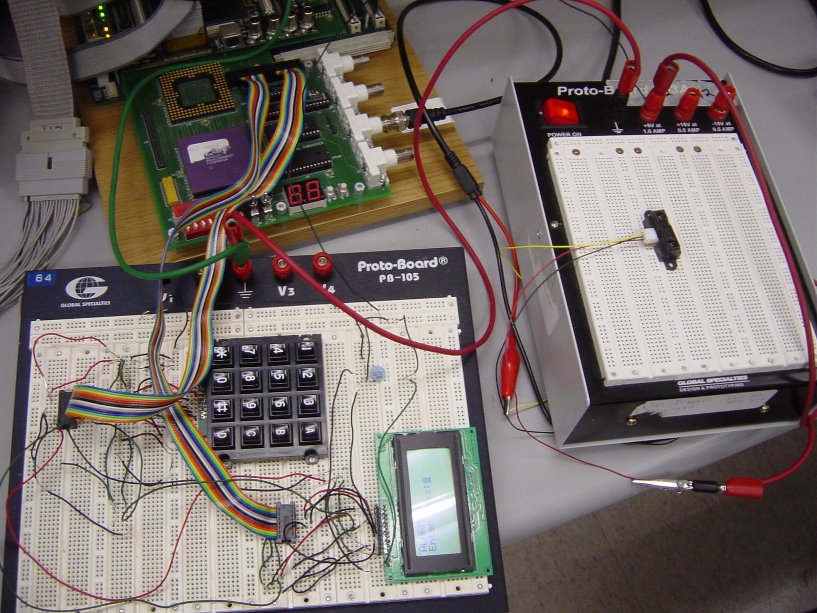
Our Home Security System interfaces with an infrared distance sensor to detect intruder’s entry into the house. The main console consists of a keypad and a LCD screen to allow users to key in password and to be notified of the system and alarm status. The console is connected to a HyperTerminal installed on a desktop PC to offer users an administrative mode. Users are then able to change the system password and to be able to find out extra information such as the error message and description of the alarm.
Project Overview
Our project setup consists of a 4x4 keypad, a LCD Character Display and an infrared distance sensor. The FPGA board is connected to the computer through the serial port to allow the use of a HyperTerminal. The user is first prompted to enter an initial system password through the HyperTerminal. This system password is needed to enable/disable the home security system. On the console, user will be greeted by a welcome screen (Figure 1). Then the user will be presented the status of the alarm and system (Figure 2). The user will then be offered the option of turning off the system by entering the right system password. If the password is incorrect, an error message is shown (Figure 3).
When the window of the house is open, the distance threshold of the infrared distance sensor will be reached and it triggers the alarm. For our project, we have set the threshold to be 0x75. Any value greater than 0x75 will trigger the alarm. When sensor is being triggered, “Alarm!” will then be shown on the LCD display( Figure 4).
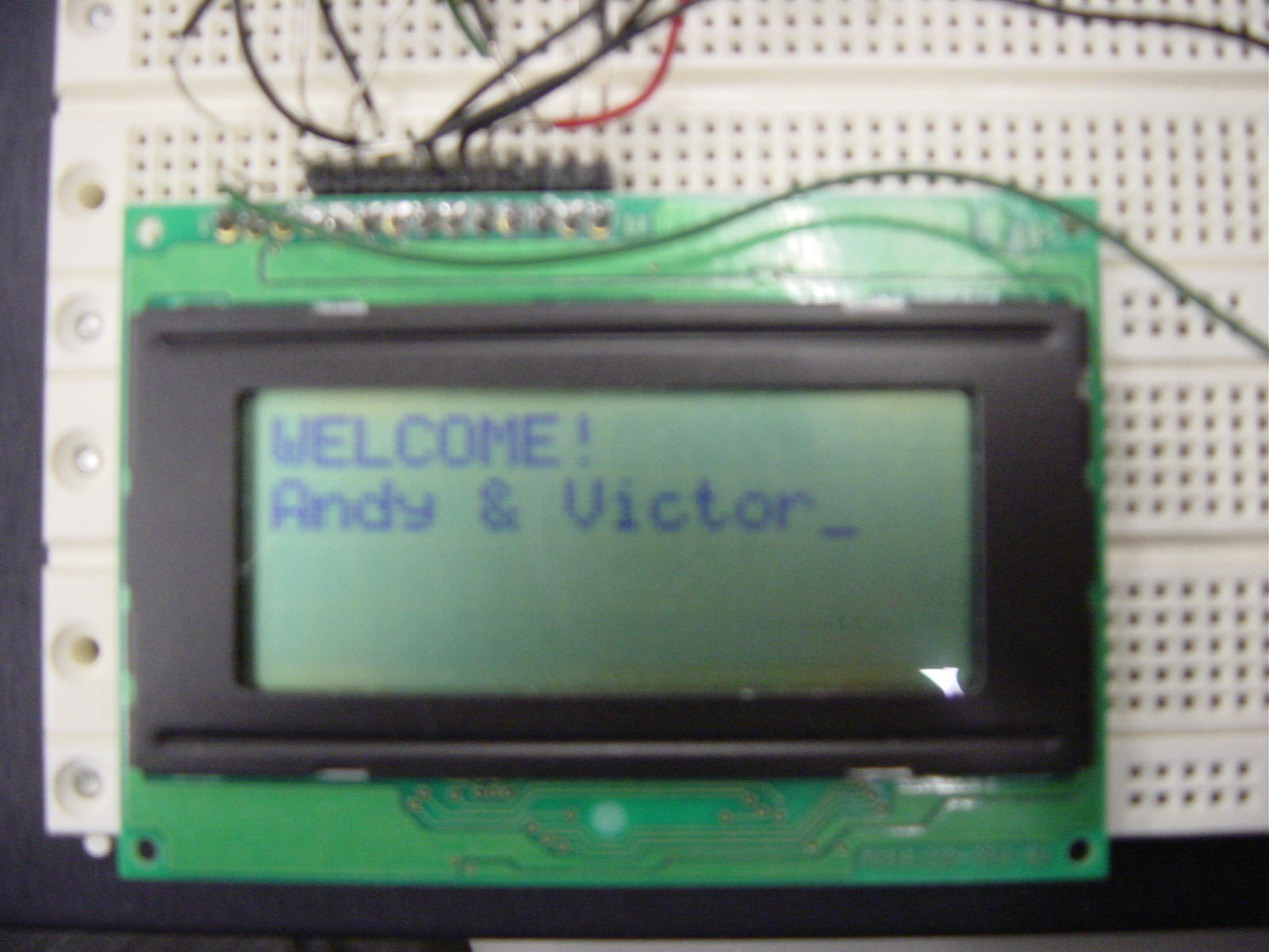

Figure 1 Figure 2
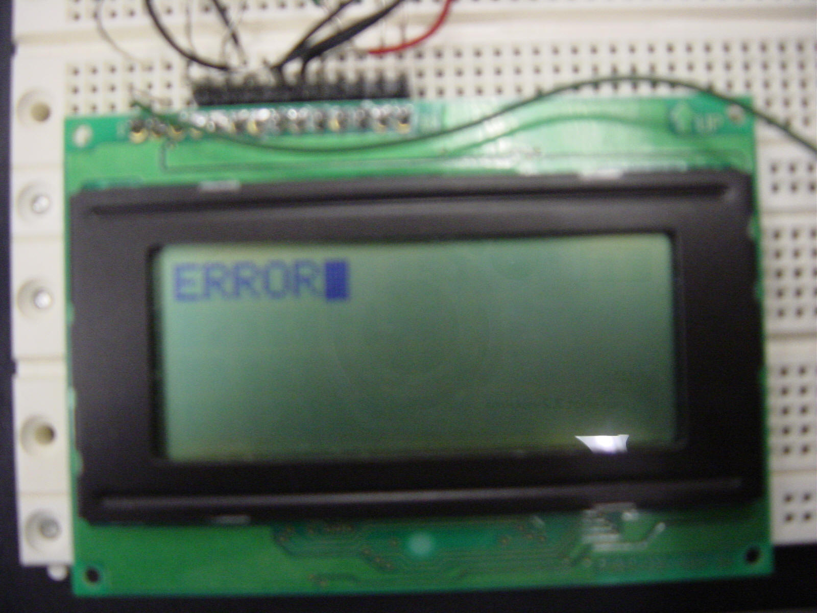
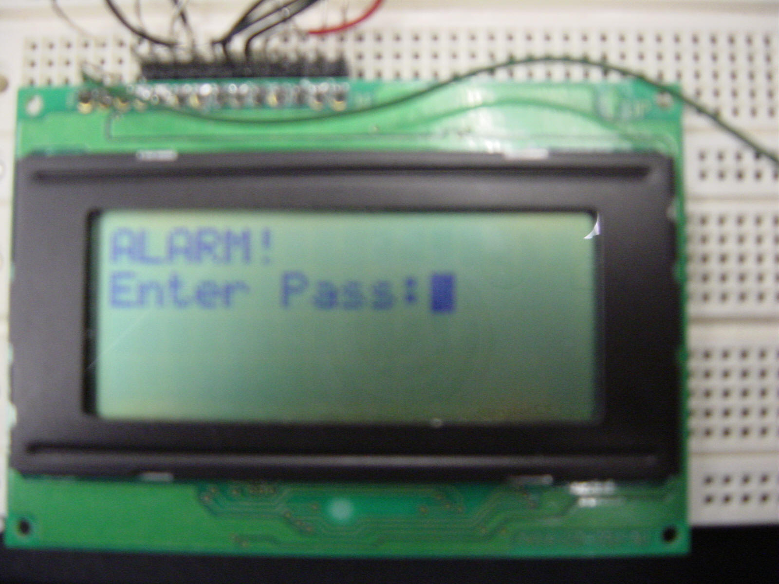
Figure 3 Figure 4
At the same time, extra information such as wrong password and alarm status will be shown on the HyperTerminal. For example, when the alarm is on, it will inform the user that the window has been opened. This allows extra sensors to be added on in future. If user has another distance sensor installed on another location, the HyperTerminal can inform user of the specific sensor that is being triggered.
System password change is also made possible through the button * on the keypad. When * is pressed, user will enter password change mode on the HyperTerminal. User will then be prompted the existing password and a new password. After the process, user will then be able to continue the system usage with a new password. Furthermore, when a # sign is pressed, the password that has been entered so far will be cleared allowing the user to reenter the desired password.
External Circuits Setup
For the keypad, we have connected pull down resistors to the pin corresponding to the rows of the keypad. When we send a high voltage to the pin of a column, buttons which are not pressed will not allow a high voltage to pass through to the corresponding row pins. The values of column are written through the test points on the FPGA board and values of rows are read through the test points of the FPGA board.
The LCD display consists of 14 pins. 11 of them are connected to the test points of the FPGA. Values are then written to the pins through the test points of the FPGA board. The remaining 3 pins are connected to a 5V power supply, ground on the FPGA board and a display contrast control. The display contrast control is connected to a variable resistor to allow contrast to be varied.( Figure 5)
The infrared distance sensor (Figure 6) is connected to the analog input 0 of the FPGA board. It is supplied with a 5V voltage and grounded with the ground on the FPGA board.
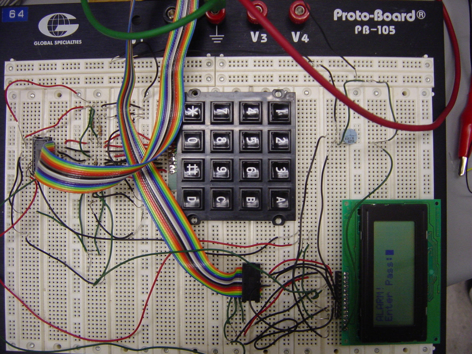
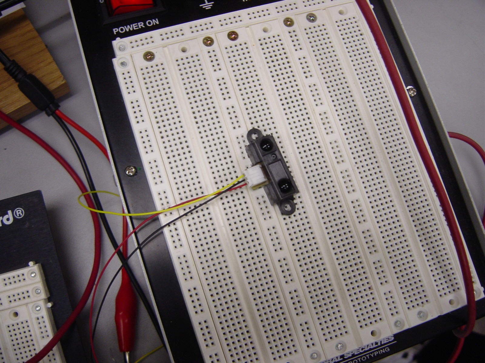
Figure 5 Figure 6