EECS 373 Final Project
George Giroux, Jeffrey Sterniak
Pinball has been around since roughly 1934. To our knowledge, no single machine has been themed around Communism and the 2004 election, so we decided to change this.
Project Components:
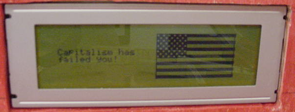
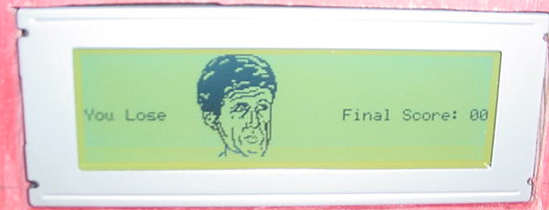
Optrex DMF5005N Character/Graphic LCD - This 240 by 64 pixel display presented the user with game information such as score and current round rank. The screen also displayed a combination of graphic and text messages whenever the player allowed the ball to get past the flippers.

Hitec Servos - Two servos served as the Iron Curtain. These twin gates blocked access to the channels behind the flippers that allowed the ball to drop directly past the flippers. As the player's rank in the Communist party rose in a single round, the gates would remain open for longer durations. An additional servo acted as the ball return mechanism. After the ball fell past the flippers, a cupcake baking tray connected to the servo by a lever arm moved the ball to a channel that placed the ball in front of the ball launcher mechanism.
DC Motors - Our DC motors, which we aptly named “The Wheels of Industry” (which are greased with the blood of the working class) were attached under our machine to wheels level with the playing surface. A wing nut, and rubber washer were then attached to the wheels. The wing nut would hit the pinball as it spun, and the washer would grab the ball as it rolled over and fling it in a random direction. The rotational speed of these motors is controlled by comparators tied to the counters we used for our gates’ timing to create specific duty cycles, and increases with the player’s point value (more specifically, upon the rank he/she has achieved within the Communist Party) to increase the level of difficulty. Finally, we have some simple switches that accumulate points as the ball hits them, and a laser with an infrared phototransistor that is tripped by the ball falling past the flippers, to activate the ball return and restart the new round.
Issues
- We faced a slew of issues with the graphical LCD display, whose fixes and general hints are covered in our comprehensive tutorial/guide document. These issues ranged from weird settings and random resets, to chopped of graphic bits in each byte and unusual offsets. The most elusive problem we faced with the LCD was probably that caused by oscillations in one of our write signals, which caused the LCD to receive and display all sorts of “interesting” characters and data.
- We would not suggest such a physical-labor intensive project to future groups. The construction and woodwork took too much valuable time away from the more 373 related components. We would have saved ourselves about a week or more of work if we had purchased an already constructed machine (which we found out afterward are actually cheaper than what we spent on materials) and added our components and/or modified existing components. On the other hand, the pinball machine pulls the components together nicely (we think).
- The servos. The pulse-widths in the specifications we read which were suggest to achieve the 90? rotation and return to idle were different from the actual widths the servos needed to accomplish these tasks. We also found that the servo, which returns the ball, probably should have been one of the high-torque servos available, as our contraption was a little heavier than we at first anticipated.
- The Wheels of Industry caused some issues. They required much more current than the FPGA put out, but we dealt with that in our circuitry—described below.
- The biggest issue, which remains unresolved, is our flipper assembly. We had originally planned to construct a system powered by two solenoids, which we would activate with pushbuttons. Unfortunately we thought we would get a jump on the timetable and ordered the solenoids on our own. We didn’t want to pay overmuch for shipping, and ended up waiting a long time for them to arrive, only to find out that they were much too weak for the functionality we desired. In the end we created completely mechanical assemblies to run the flippers, which was very time consuming and ended up not working very smoothly, though they still have the bare-minimal functionality necessary.
- We also encountered an issue in several places with the current and voltage levels produced by the board (and the discrepancies between the boards in these levels). We resolved this using our external circuitry, and by finding a board that produced a sufficient voltage to keep our LCD from resetting itself at frustrating times.
External Circuitry:
Besides the basic wiring and pull-up resistors we used several components of our external circuitry to fix problems and/or account for issues we ran into in our implementation process. For each of the Wheels of Industry we used a CMOS chip and a transistor. The first was to provide the necessary current level (approximately 300 mA) to run the DC motors. The transistor was to provide voltage amplification to bring the voltage level produced at the test points to the level required by the relay. These combined to provide our Wheels with the necessary current and voltage levels to operate as desired. For the contrast level on our LCD we used a 10 k? potentiometer, and to get the correct operation from our infrared phototransistor we used a comparator IC. The comparator eliminated the noise created by ambient light in the room, so that we would get a clean break as the ball rolled past the laser, thus tripping the end-of-round and ball return sequences.
Project Approach:
Our approach to the project was rather straightforward. We first created the hardware design, in Xilinx and with the necessary external circuitry, to run the servos and LCD. The LCD was our first goal, as it was entirely new, and we wanted to make sure we had time to master its complexities to tie it nicely with the rest of our design. Our problems with the LCD settings ended up meaning we had the servos properly working before we finished the LCD though. Next we began designing the physical layout for the pinball machine. Most of the materials we used were plywood, Plexiglas and 2x4’s scrounged from the homes of family and friends. After creating the base and constructing what we thought was a very cool ball launcher, we came up with layouts for the game, such as where the flippers, gates and ball return would go. At about the same time we began basic programming for integration of the electromechanical parts into a seamless whole. The problems we experienced with construction and with implementation of the integration are mentioned above, but at this point we also began to set up our switch series and create areas for the laser and phototransistor. In the end, we fixed the problems with our current and voltage levels, eliminated noise from our switch signals, accounted for oscillations in some of our signals, and successfully completed integration. The biggest shortcoming in our approach would probably be our lack of planning when it came to construction. We ended up designing and building each piece individually and attaching them to the machine, whereas we should have had a clear plan from the get-go, which would have saved us a lot of time and mess (this in reference to the woodwork and physical construction; our electronics and programming were better planned)
Project References:
Most of the references used were available in the lab. The one item which we used specifications for was the graphical LCD. We encountered enough vagaries and discontinuities in the usage and control of the character set, the graphical modes and settings, etc. to warrant creating our own guide to the basic successful implementation of the integrated character set and user-defined graphics for use as a reference.