|
Dave
Belding and Kelsey Hill Ever had
your last bit of coffee burn up in the pot? You get down to those last few
drops and the coffee pot doesn't lower its temperature at all and soon all
you have is burned coffee and a scorched pot.
|
|
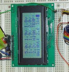
The LCD The LCD was the hardest part of the design of our Smart Coffee Maker. It requires slowing the bus down to 10 MHz (a simple setting in the SCCR register) and stretching timing out on all signals to accomodate the slower timing of the LCD controls. Once timing is properly set up, there is an initialization sequence that must be sent to the LCD as the first thing when it is powered on. This involves picking a function set, setting it for 8-bit data, and setting the cursor direction. |
|
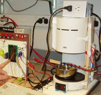
There are 7 thermistors across the plate on the coffee maker. In a real design, the thermistors would be built right into the plate to take an actual temperature reading, but due to manufacturing constraints, we installed ours above. These are links to the protoboard, each in series with a 200 kOhm resistor. Voltage from across the resistors is sent to 7 of the 8 channels of the ADC and converted by software into a temperature reading. |
|
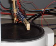
There are two weight sensors on a protoboard under the coffee maker. One is just for balance support for the other which actually provides a voltage readout to the ADC, again across a nother resistor. This makes it output more voltage as more weight is applied. Again, in a real design, these would be built in under the plate to measure the weight of the coffee in the pot. |

|
The relay switch is set up with a transistor circuit. The gate on the transistor is connected to one of the test-point pins so when it is sent a 1, it allows power to go through the transistor to the relay. This is used to turn the coffee maker on at the beginning and to turn it off if the weight/temperature ratio becomes too small. The circuit can be seen in the picture, with the green wire at the top of the LCD. |
|
Software The
majority of our software is implemented at the assembly language level. The temperature sensors and weight
sensor are read from the ADC on 2 ms interrupts and their values are stored
into an array. This array is
processed by a C function called format.c that turns their hex values into
something that can be outputted to the display. Due to timing issues with the LCD, this is not all
outputted at once; instead it is implemented with a 1 ms timer which
essentially runs through the formatted array, writing it to the LCD screen. The LCD is
also initialized through an interrupt generated by a timer. Because of certain timings required
by the LCD initialization process, the interrupt is generated every 6 ms. Our final interrupt is external, using
IRQ7 for the end of conversion (EOC) signal from the ADC, letting us know
that our conversion is finished. Difficulties |
|
|
|
* Bad cables, pins, protoboards. We made the mistake of building
our circuit right on a powered protoboard, assuming that because it only
worked for 5 volts and no one else needed it, it would be easiest and most
compact to just build our circuit right on it. The problem arose when our
protoboard starting only outputting about 0.9 volts instead of 5, which is not
enough to power our LCD. |