Instrument TunerDocumentation |
Gregory Chen
Lawrence McAfee
![]()
For our project, we designed a system for tuning instruments. The system can be used for tuning of all notes in the middle octave, since this is the range of notes that is most commonly used for tuning. Notes A or Ab are the most commonly used, but for versatility and use among multiple instruments, the entire range of notes was used from Ab to G. On the highest level, the system consists of a microphone for reading in sound signals, the processor measures the frequency of the note, and the note being played is displayed on the character display to let the user know if he/she is in tune.
The frequency of the signal is measured by measuring the frequency of occurrence of an interrupt signal that is caused by the sound signal. The system is setup so that an interrupt is thrown each period of the waveform so that the frequency of occurrence of the interrupt signal is that of the note being played. As mentioned, the sound signals were inputted to the system by the microphone. From the microphone, the signal goes to the the saturation circuitry that works as follows: when the signal is above a certain voltage, the circuitry output is a logical 1. If the signal is below a certain voltage, the circuitry output is a logical 0. The signal at the output of the saturation circuitry controls the IRQ interrupt signal of the MPC823. The MPC823 then uses software to measure the frequency of occurrence of the interrupt. Then, depending on the measured frequency, a note is displayed on the character display corresponding to the frequency of the note being played into the microphone.
Gregory Chen
Lawrence McAfee
The standard EECS373 Omnidirectional Electret Condenser Microphone Cartridge was used for input of the sound wave into the system.
An LM741 op-amp is the heart of the saturation circuitry. As mentioned, the circuitry outputs a logical 1 when the input voltage is high enough and logical 0 if below this threshold. In essence, since the sound signal is sinusoidal, the saturation circuitry is logical 1 for each peak of the sound signal and therefore outputs a logical 1 in a string of logical 0's so that the logical 1 occurs at the frequency of the sound signal. The circuit model for this stage follows the circuit shown on slide 46 of the F05 Project Overview Slides.
The Optrex DMC16433 character display is used for displaying of the current note that is being played into the microphone. The hardware for writing to (and not reading from) the display is implemented . The hardware is responsible for creating the signals to be sent to the display with all timing requirements met. The hardware is memory mapped. One address is for writing to the instruction register of the display, while the other address is for writing to the data register. Timing requirements pertaining to time between writing to the character display registers are taken care of by the software.
The software was used for setting up interrupt registers and enabling interrupts on the MPC823, setting up the timer registers, determining the frequency of the incoming interrupt signal, determining which note on the music scale it correlates to, and writing this note to the character display.
Note Determination
As mentioned, the external IRQ interrupt signal is asserted at the frequency of the current note being played. This frequency of occurrence must be measured in order to determine the frequency of the note. This frequency measure is performed by using one of the MPC823 timers to count the number of clock cycles that occur between each interrupt signal occurrence. Initially, timer1 was setup to count up once per clock cycle so almost the exact number of clock cycles is recorded. However, this once-per-clock-cycle method was slightly changed, as explained in the "Results" section. Whenever an interrupt occurs, the ISR takes the value from TCN1, and immediately resets the timer. Resetting at this point ensures the most accurate measure of the number of clock cycles between interrupt occurrence.
The ISR uses this timer count value with a table of count values to determine which note is being played. Each note has a range of count values that corresponds to that note. One thing that needed to be ensured was that overflow of the timer did not occur, or else accurate timer count values would not be recorded. Meeting this requirement was made possible by using only the middle octave, which as mentioned is the only octave needed for tuning, for use with the system. The 16-bit counter can count up to 65,536, and the highest count value corresponds to the lowest included note frequency, Ab, which requires 48,158 clock cycles. each higher frequency requires fewer clock cycles. Also, the number of clock cycles to run the ISR was considered since a long enough ISR could potentially require as many clock cycles to complete as a high frequency note. Again, using the middle octave ensured this overlap would not occur.
The software then uses this note determined from the table in another table for determining the character code value to be sent to the data register of the character display. Since the read function of the character display was not implemented, the software incorporates a wait function to meet the timing requirements of the display. The wait function is used between writes to the instruction register and data register of the display.
C and Assembly
Assembly was used primarily to setup registers needed for the interrupt and timer. Assembly was also used for loads and stores, including storing to the character display registers. Outside of that, C was used primarily for everything else. This includes the two tables for looking up the musical note, and for looking up the corresponding character code for the character display. We divided it up like this because writing to processor registers is easier in assembly, but everything else seemed to be easier to do in C.
We initially had problems with recording inaccurate values from the timer. This was because we were resetting the timer at the wrong time. The timer was being reset at the end of the ISR as opposed to the beginning of the ISR, causing the timer count value to be off by thousands of cycles. This large discrepancy in cycles came about from the wait function, which loops through thousands of cycles to pause the processor.
The next problem we had was not having reliable timer count values. Sometimes the timer count value would be correct, but other times it would be thousands of clock cycles off. Often times this would happen in an oscillatory fashion, going back and forth between the correct value and some constant incorrect value from one run of the ISR to the next. From watching the IRQ signal on the oscilloscope, we found that overflow was occurring due to higher frequency notes (above middle octave) for these incorrect timer count values. We corrected this by slowing down the timer to count at 1/256th the speed it had been counting, eliminating overflow by not allowing the timer to count to anywhere close to 65536. However, since we redefined our system to work only for the middle octave, this correction ended up not even being needed.
We were able to implement an instrument tuner for tuning all notes in the middle octave of the musical scale. Currently, the software is almost setup for determining notes in several lower and higher octaves. However, in the current state the lower octaves do not always operate properly, and given that for tuning other octaves would rarely be used, leaving out these extra octaves does not take away much from the overall purpose of the system.
A potentially more robust and versatile method of creating the system would have been to use the Fast Fourier Transform. Then, multiple frequencies being played at the same time, such as in a song, could be recorded. However, implementing the FFT in assembly language would have required more time than we reasonably could have devoted to the project. Nevertheless, with the current method of using timers for frequency measurement, the system works as necessary for tuning notes.
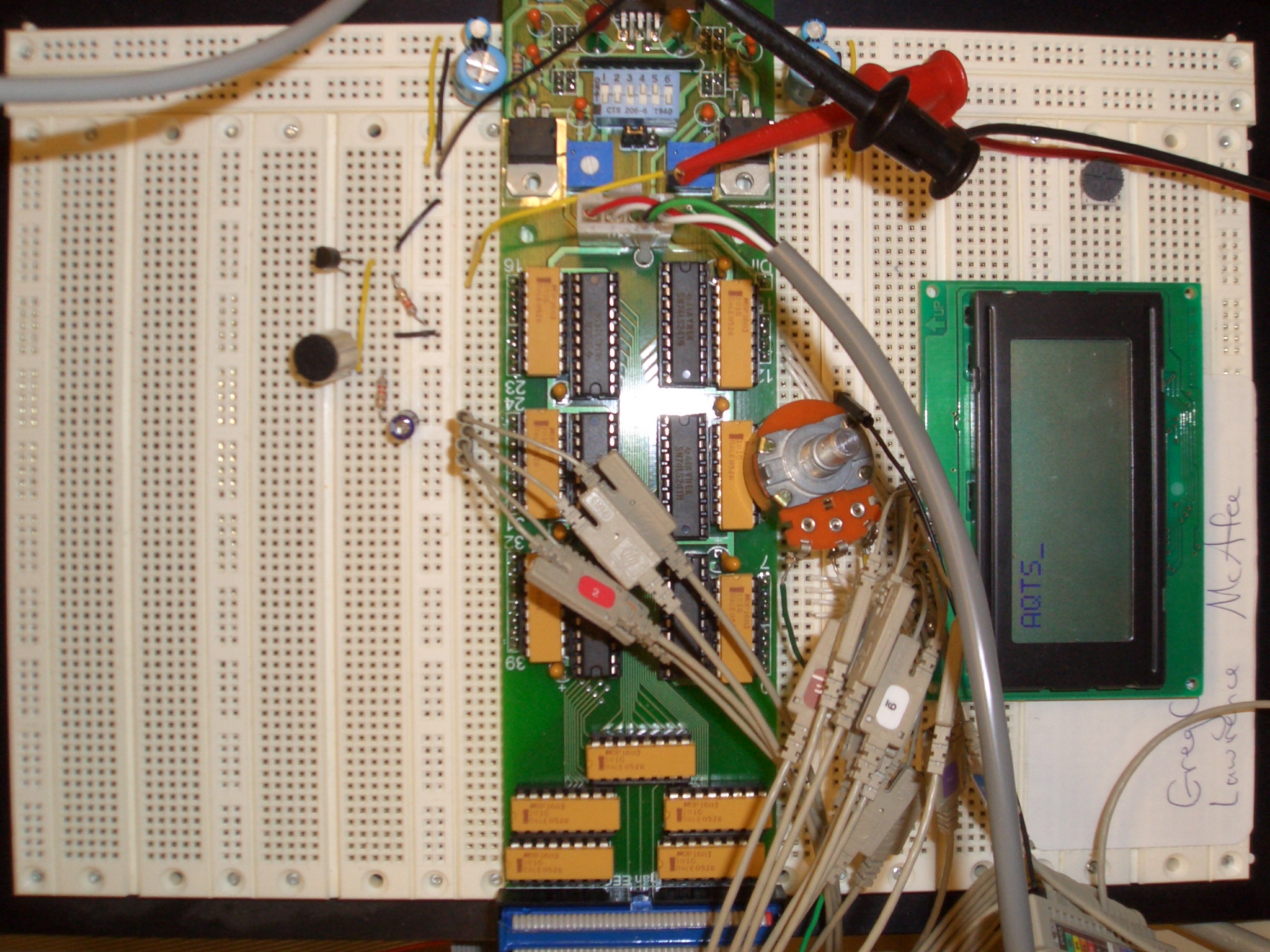
Musical note being displayed on character display
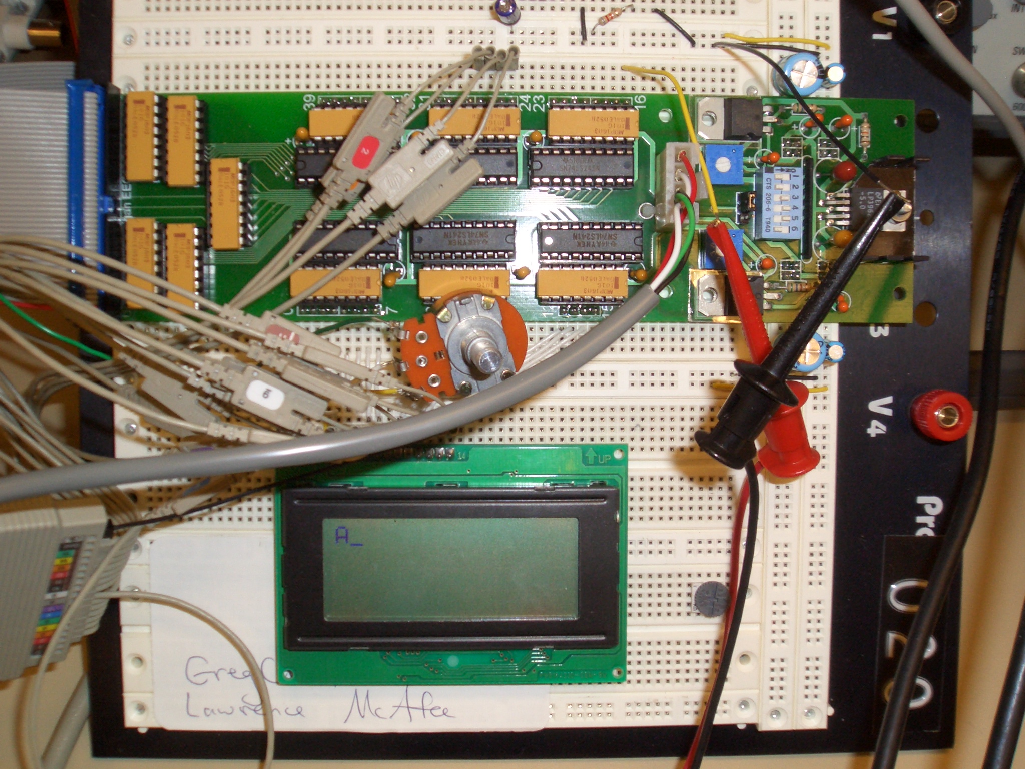
System components: microphone, IO expansion board, character display
» F05
Project Overview Slides
»
General Optrex Manufacturers Spec
»
HD44780 Controller Spec
»
Musical Notes and
Frequencies