| |
EECS 373 WINTER 2006 FINAL PROJECT |
Light Tracker by Wilson Ng |
|
|
 |
| PROJECT DESCRIPTION |
|
The major objective of this project is to create a device that's reactive towards light. Abstractly speaking, the mission of this project is to emulate the behavior of a "sun-flower", which is able to detect a light source, and hence turns itself to face the light. If the light source moves, the "sun-flower" should make proper angular displacements so that it's always facing the light source.
In addition, a Nintendo 8 controller could be added to system, facilitating manual controls on the rotation of the "sun-flower".
|
|
|
| PROJECT COMPONENTS |
|
| The primary components of this project consist of the servo, the photo-resistors and the Nintendo 8 controller. |
|
| Servo: |
 |
The servo is a functional unit that allows mechanical rotations. When centered, the servo can provide up to +/- 60 degrees angular displacement.
In brief, the servo requires a 5V power supply (RED wire: 5V; BLACK wire GND) and a pulse (YELLOW wire) to define its angular displacement. To fix the servo at a certain angle, a constant pulse to be fed to the servo every 100 ms. Ideally, the width of the pulse should be linearly proportionally to the angular displacement.
Based on project experience, pulse widths range from 0.6 ms to 2.2 ms every 100 ms. |
|
| Photo-resistors: |
 |
The photo-resistors are light-sensing units for this project. Their resistances vary with respect to the amount of light shed onto them.
As for implementation, for each light-sensing node, the photo-resistor is connected in series with another fixed resistor. Then 5V is applied across the circuit. As the amount of light shed onto the photo-resistor varies, the resistance of the photo-resistor varies, and thus the potential difference across the photo-resistor also changes.
Therefore, by measuring the P.D. across the photo-resistor, the amount of light shed onto it is indirectly known. |
|
 |
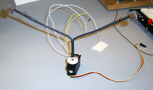
Since the "sun-flower" has 2 arms, 2 photo-resistors are used, one on each arm's end.
In general, if the "sun-flower" is facing the light source, then the 2 photo-resistors on both ends should be shed approximately the equal amount of light. As a result, continuous adjustments on the angular displacement of the servo are made to maintain the balance between the readings of the 2 photo-resistors. |
|
 |
The photo-resistors are modulized to enable "plug-n-play" features.
The photo-resistor contains the pins. |
|
 |
The arm's end contains the pin heads. |
|
 |
The photo-resistors can be plugged to either arm's end. |
|
| Nintendo 8 Controller: |
 |
The Nintendo 8 Controller is used to manually control the rotation of the servo.
The "Select" button on the controller is for switching between "Light-sensing" mode and "Manual control" mode. |
|
 |
As the states of buttons are received through one serial data line, pulses are used to latch in the states of each button one after another. |
|
|
|
| PROJECT INTEGRATION |
|
Getting each of the components to work independently could be trivial, while getting all of them to work together is relatively more challenging.
DEVICE WALKTHROUGH
(i) Detecting the Environment:
First of all, readings on the 2 photo-resistors are polled to determine the biased position of light source. To achieve this, the analog voltage readings from the 2 photo-resistors are simultaneously converted to digital signals for processing. The digital signals are then compared and the difference between the 2 signals is calculated as the delta. The greater the delta, the more biased to one side is the light source.
(ii) Rotating the Servo:
By analyzing the delta, the position of the light source could be approximated, and hence a corresponding pulse width could be fed to the servo for adjusting the angular displacement. This is done by changing the Timer Reference Register so that timer interrupts are caused at different times.
(iii) Nintendo Controller:
Aside from light detection, angular movement of the servo can also be controlled by the Nintendo controller. When the "Select" button is pressed, the "sun-flower" switches from "Light-sensing" mode to "Manual control" mode and vice-versa. The "Left" and "B" buttons are for turning the servo clockwise while "Right" and "A" are for anti-clockwise turns. |
|
|
| DIFFICULTIES AND ISSUES |
|
(i) Photo-resistor Sensing Range
The range of the photo-resistor is really small. Basically, the resistance of the photo-resistor does not change much unless the light beam is focused directly on it.
(ii) Servo Glitches
Ideally speaking, when fed with a constant pulse per 100 ms, the servo is supposed to remain at a fixed angular displacement. However, in practice, for certain pulse widths, the servo is a little bit unstable and glitches back and forth. |
|
|
|