Putt-Putt Golf
Members:
Rajesh Kulkarni (prabhaka), Sash Nagarkar (sashn)
Introduction:
The main point of this project was to create a putt-putt golf game using a graphic LCD display and a Nintendo 64 controller. Both us are a big fan of putt-putt so this seemed like an interesting project. Our first major goal was to have the graphics work in real-time and at the same time maintian a high fps. We had been told from previous semesters that this would be a diffcult task. We also wanted a wide assortment of inputs in our game, so we decided to use the Nintendo 64 controller which has an adequate selection of buttons that we can use.
High Level Design:
LCD Graphics Display Controller - For this project we decided to go with the 240x64 graphic/text display. This LCD provides us a graphical display of our game in real time with animation. There are both software and hardware components to our LCD.
Nintendo64 Controller - The Nintendo 64 controller serves as our only input source since it is only a one player game. Pressing the B button brings up a brief help menu. The directional pad and the C-buttons change the direction in which you want to hit the ball. The A button controls the strength and accuracy meter. If you want to see your score card for the current game, you can simply press the Z button.
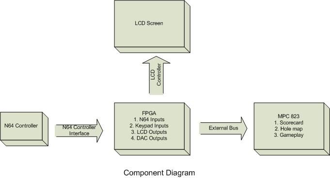
Here is a high-level diagram of our project:
Hardware Design:
Graphic Display - In order to interface with our LCD we bascially created a macro in Xilinx that would handle both reads and writes to our display using one base address location. By specifying an address we can send data or commands to our LCD. Reads would essentially work in the same fashion except we would need logic to drive the PD_OUT_EN pin. The LCD basically acted like one large memory bank where when we wrote to a certain pixel,which was mapped to a memory location. By setting or clearing the specified bit, we could control the images displayed on the screen via bitmaps or draw functions. The main constraint on the LCD was the timing requirements for both reads and writes. We found this part to the be most challenging. In order to create timings that were in spec we used a series of flip-flops to extend our signal to a given time. It is important to note that our timings were based on a divided bus clock of 100ns or 10Mhz. In order to generate TA_BAR and PD_OUT_EN we used the same series of flip-flops and sampling the value at the correct time and sending it to the processor. We obtained the various timings from refrences that we will mention later. Along with handling the timing issues, this macro interfaced with IO expansion board using the macros that were given to us. We also had this macro connected straight to the MPC823's buses, PD_IN and PD_OUT. We also had to physically wire the LCD to the IO Exapnsion, and while this may seem like an easy task it had its issues.
N64 Controller - In order to interface with the Nintendo 64 controller we wrote two modules in Verilog. The first module would be responsible for transmitting the get_commands button to the controller. If this was sent correctly the controller would respond back with 32 bits on data encoded according to the controller specification. The N64 controller works on a microsecond based clock while our bus runs on nanoseconds. So in order to interface with the controller we would have to introduce wait states. In order to acheive this we essentially created a state machine that would wait a set amount of time before transmitting a valid bit. This method seemed to work well for the transmitter. The hardware essentially loopped through and sent the get_buttton command every 1.2 msec. We felt that this would be an ideal delay for the type of game play we expect. After we are done sending the get_button command we hand the controller over to the second Verilog module that is in charge of taking the the received data and storing the serial bits into a bank of flip-flops. One quirk was that since the N64 data line is bi-directional the receiver saw everything we were transmitting. The receiver was setup much like the transmitter in that it was based on a state machine that would essentially loop through the singal and find out what bits were set based on the timing spec. What makes detection do able is that fact that you can expect your data bit to be present after you see a neg edge and wait around 2 microseconds.
Software Design:
Device Drivers:
N64 Controller - This driver reads from the N64's address and returns the value stored in the N64 receiver flip-flops from the most recent get_button command. The software reads this data ten times and collects it in an array, which is then passed through a majority algorithim that will determine which buttons were pressed. This method was used to offset glitches from our hardware and the controller.
Graphic Display - The display requires a detailed and rigid set of steps to perform initialization, and to execute the setting/clearing of bits according to the specification. This device driver is able to read and write commands or data to the specified controller address. One of the biggest problems with the provided display is that it only supports a 6x8 font size, which means that for every 8 bits that are written on the display's data pins, the upper two bits are ignored. This poses a significant problem since it affects even the graphic data display. Since we were optimizing the design so that we could quickly set or clear pixels on the screen, the method employed was to move the current address pointer to the specified pixel, and then to use the bit set/reset command on the pixel that is chosen. We found this to be significantly faster than keeping a map of the entire display in the MPC823's memory and rewriting the entire array to the display whenever it is modified. Based on this setup, we created functions to draw lines, boxes, and bitmaps on the screen that we then used to create the game map and intermediate screens.
Game Design:
We used the graphic display device driver to write specific bitmaps and boxes to the screen, and the N64 controller device driver to obtain the user input. When the user pressed a button, it was processed and the display was appropriately updated. We created a power-bar that is found in many games today, which starts with the B button, and has to be stopped at a certain location to obtain a level of power and accuracy. The putter then hits the ball, which moves in the specified direction, and bounces off objects that are encountered. This was all done algorithmically based on the overall map design. The scorecard is updated to reflect the shot or hole, and the game continues.
Results:
With the hardware that we integrated we were very pleased with the results. Our LCD was able to draw a ball and send it on a trajectory with motion that looked pretty realistic. We made very good use of the LCD features. We were able to draw a single pixel, lines, bitmaps, or boxes to the screen where ever we wanted, as well as clear those same drawings with a single command. We could also read from any location on the LCD. With a few tweaks here and there we were able to get the N64 to work properly. We essentially sample the controller input 10 times and do a majority poll to check whether each button was pressed. This way we were able to avoid random bit flips that occured in our hardware. One issue that was still left unresolved was the fact that the N64 controller would return bogus values when we hadnt pressed anything. Overall our hardware performed to our expecation.
Conclusion:
Yes it is possible to implement our idea with the components we used, but in order to have smoother graphics you might want to use a LCD that has DMA access so you can speed up transaction time. While we found the LCD response time adequate for our needs, we had to struggle to manage bus bandwith resources to achieve our results. As for processing power we think the MPC823 worked well for the most part. Our biggest stumbling block was that fact that our ribbon cable for LCD was bad the entire time. We wasted a little over a week trying to fix it. We would advise that people check their cables and components before (and while) using them since wiring/timing mistakes can somtimes break devices. The N64 controller polling method was also a bit of a hack that we had to use and would have liked to avoid since it decreases the sensitivity of the user input.
Media:
[Movie]
References:
Most of the references we used were directly from the class website, especially for the LCD controller. The following however, is a great place for N64 controller layout information:
http://www-inst.eecs.berkeley.edu/~cs150/fa05/Labs/Checkpoint1.doc