Tic-Tac-Toe Robotic Claw
By Scott McLelland and Jingyang Xue
Introduction High Level Design Task Contribution Hardware Design
Software Design Design Result Media Video Conclusion
Everyone is familiar with the game of Tic-Tac-Toe. There is a 3x3 grid, and two players take turns placing pieces in attempt to get three in a row. In our project we created a robot that could play Tic-Tac-Toe against a human player. To do this, we used a robotic arm to pick up the pieces, a specially made board and piece to detect piece placements, and an LCD screen and two pushbuttons to relay information from the computer to the user and visa versa.
Our design consists of the main components listed above: a robotic arm which is controlled by 5 separate servos, a specially created board to detect piece locations, an LCD to display relevant game information to the player, and two pushbuttons to select pre-game options and to signal that the player has made a move.
We also had a fairly simple algorithm that could be run on one of three difficulties to select the next piece to be placed given the current board position. Once it selects a move, it calls the appropriate pick up and placement routines for the claw. We had 5 pickup routines to pick up each of the 5 computer pieces, and 9 placement routines to move the piece to any of the 9 board locations.
Scott: Servo PWM hardware design, robotic arm calibration, LCD driver, piece fabrication
Jingyang: Board setup, board interface hardware, piece detection drivers, LCD hardware, computer strategy algorithm, piece assembly
Board Detection Hardware:
We constructed our own board to detect what piece is being placed down. There are total of 9 squares on the board, and we numbered the top 3 squares 1, 2, 3, respectively, and the second row’s squares 4, 5 and 6, and the last row’s squares 7, 8 and 9. The overall scheme is that we have 3 power lines that feeds into each of the 3 columns, and we read out the value of the board on the 3 rows. Each of the 9 squares acts as an open circuit when there is no piece being placed. When a piece is placed, the circuit completes, and we will read a one on that row. Likewise, when a space is empty, we want to read a zero. To prevent the node from floating, we have 1k pull down resisters to pull the line to ground, and we read the value before the pull down resister. For example, if we want to detect whether there is a piece on 5(middle position), we feed Vdd into the second column, and see if we detect a 1 on the second row. The columns will be sampled from left to right in order to determine the value on the entire board.
A complication of this design is that, if positions 1, 4 and 5 have pieces, and we are trying to check which ones in the second column have pieces. We will feed a 1 to the second column, position 5 will have a short, and the current can travel to the left to position 4, and since there is a short there, it will travel upwards on the power line to reach position 1, find another short, and travel to the right to position 2. Even if there is no piece on position 2, we will always falsely detect one. To prevent this sort of loop, we placed a diode for each position between the copper piece and the read out wire. In this way, current cannot travel up, and prevents false detection.
The interface hardware for the board is relatively simple. We used the address 0x02600010 as the IO mapped address. A write to this address will supply 3 bits of data that correspond to the three power lines. 1 is Vdd and 0 is ground. A read from this address will send the read out value onto the data bus. This value also has 3 valid bits. Bit 0(MSB) shows if the top row has a piece, and bit2(LSB) indicates if the bottom row has a piece.
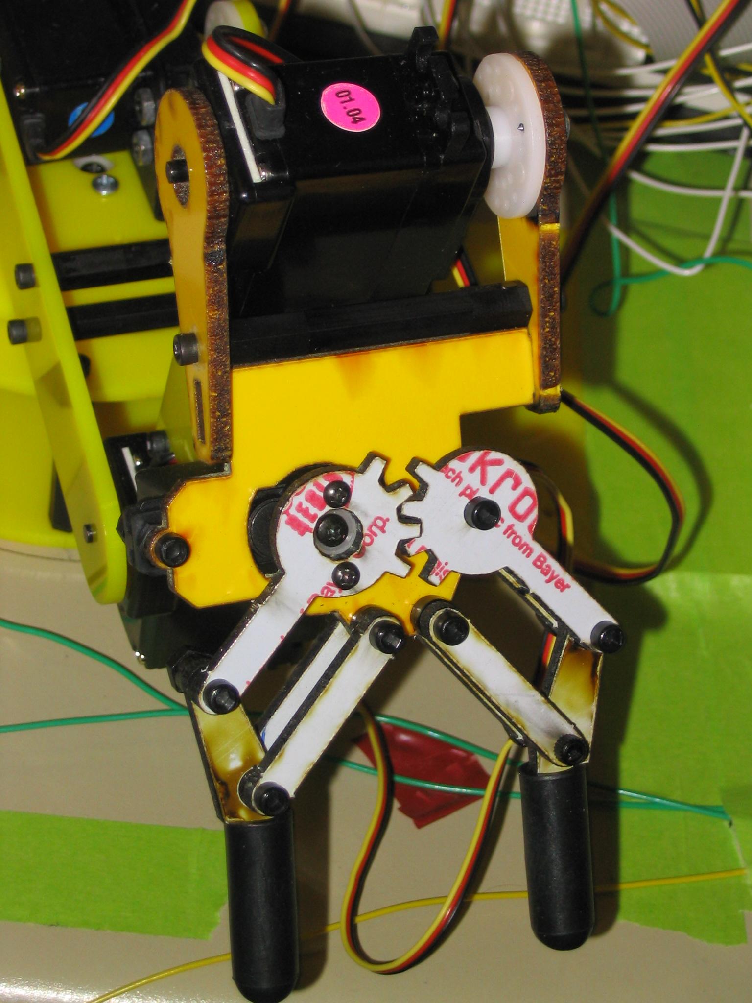
Robotic Arm Control:
The robotic arm was controlled by 5 servos, 4 large servos for movement and one micro servo for claw control. There was a provided controller, but we chose to implement independent pulse width modulation for each of the servos. Since we needed 5 independent PWMs and only two timers were provided, we had to make a custom circuit to generate them. The servos required a 60 HZ signal with a pulse anywhere from 0.5 to 2.5 ms which we generated using a memory mapped register that controlled the servo pulse. The provided controller used values form 0 to 256, and we did the same, only adding an offset of 64, so the values stored in the register were anywhere from 64 to 320.
We used two counters, one 8 bit used to split the original clock by 192, and a 16 bit counter to control the PWM generation. The second counter value was fed the slowed down clock, and compared to both our variable register value and a set value that determined the end of a period, such that our signal was 60 Hz. When the register value was reached, we dropped the signal low, and when the set reference value was reached, the signal was set high and the counter reset.
Using this hardware, and a slight modification of the calculator program from lab, we were able to control the robotic arm via the HyperTerminal, and map out the movements necessary to pick up and place all of the computer pieces. This calibration of the robotic arm will be discussed in more detail in the software section.
LCD:
We used a 4x16 character display to generate pre-game selection options as well as error and game end messages. The hardware for this is straight forward. The IO mapped address 0x02700000 is used. We hooked up the pins according to the specification and constructed the interface timing according to the manufacturer’s timing diagram. For simplicity, we only created the write portion of the hardware, since reading from the LCD in our case was unnecessary.
Pushbuttons:
The hardware for the pushbuttons was very simple. We have one pushbutton that is hooked up to the expansion board and use S2 on the main board as our other pushbutton because we never had time to get another button made. The first pushbutton behaves exactly as the S1 and S2 buttons work, but is connected to a test point input. We have address detection logic to generate PD_OUT_EN and TA_BAR so that we can read from the external pushbutton. It is hooked up to IRQ1 because it is used as an interrupt in the beginning of the program when options are selected, and also hooked up via a tri-state gate to the data_out line so that we can read its value in the main program. S2 is hooked directly to IRQ7 because it is only used in the beginning of the program to cycle through our LCD menus. A more complex explanation of our pushbuttons and the interrupt scheme can be found in the next section, Software Design.
Board Detection Method:
The assembly writes a 1, 2, 4 to address 0x02600010 to read the left, middle and right columns in 3 turns, and does a read to the same address to read the board values back. A binary search scheme is then used. The value returned from the board for each column is between 0 and 7. If the value is great than 4, there is a piece in the top position of the column. We store the piece’s value in memory, then subtract 4 from the read-back value. We then compare the remainder to 2 to check if the middle position is occupied, and then to 1 to see if the bottom position is occupied. For the nine positions on the board, we use memory locations 0x03200008 to 0x03200072, each 8 bytes apart, to store the values. This is done for the ease of reading the values in memory when we are debugging. A value of 2 indicates the position is still empty. 0 means the O-player, or the computer occupies the space, and 1 means the X-player, or the human occupies the space. If there is a piece present as indicted by the detection hardware, we first check if the memory has the value of 2. If not, we do not write the value. This will eliminate possible detection error of the board.
The C code portion of the detection logic first reads the entire board. The getboard assembly function takes a piece position indicated by numbers 1-9, and returns the value of the board stored at that piece position. Then the C code stores the values in its 3x3 matrix which all its other functions use. After the computer makes its move, the position of the piece is returned to the assembly function,
Robotic Arm Pickup and Placement Routines:
To facilitate easy pickup and placement of the pieces by the robotic arm, we wrote pickup and placement routines for all of the locations that the arm needed to go. That corresponds to 5 pickup routines and 9 placement routines for the 5 pieces and 9 squares respectively. The routines were very simple C functions, each one simply consisting of servo placement calls such as “servo1(100);” and calls to a sleep function to make sure the arm finished its current move before making the next one.
The individual servo calls were done in assembly and were also rather basic. They simply took the input value found in r3, and stored its contents + 64 into the corresponding register. We used memory locations 0x03400000 to 0x03400010 for the servo control register, each register being a half word.
So far this probably sounds easy, but the hard part was calibrating the arm to figure out what sequence of moves would take us to each location on the board. To do this, we modified the calculator program so that we could input exact numbers via the HyperTerminal. To make it work, you had to input “M 5 5 5 5 170” or something to that extent where each number was for a different servo, 1-5. In this case, that would put the arm at its starting position. Using trial and error, we were able to map out the move sequences to all 14 places.
In order to be able to place the pieces after pickup with only one routine regardless of where the pieces were located, we had all of the pickup routines end at a common location, so the placement routines would work the same regardless of which piece was picked up.
LCD Display:
Our LCD display control software was all written in assembly. We had three menus that would be accessed in order, and the two pushbuttons were used to navigate the menus. The three menus were the welcome screen, the main menu consisting of selecting who goes first or exiting, and selecting the difficulty. Our external button was used to select an item and S2 to see the next item in the menu. First, we had to write simple functions to initialize the display, clear the display, and print each of the messages we wanted on the LCD.
The actual program first calls the initialization code and then prints the welcome message. It then contains three main loops. They all check memory address 0x03200000 to see if it is a 1, and if so break out of the loop. At the beginning of the loop that value is set to 0, and it is only set to 1 when an IRQ1 interrupt occurs (the external pushbutton).
Then the code clears the display, prints the next menu option, clears the loop bit, and enters the next loop.
If S2 is pressed, triggering an IRQ7 interrupt, the interrupt code figures out what menu is currently being displayed, and displays the next option in that menu. If it is already at the last option for that menu, nothing is displayed. If it is in the difficulty menu, it also stores the current difficulty value, and if in the main menu, stores who should go first.
Once the third loop is broken out of, the EE bit in the MSR is disables, so that the two button pushes no longer generate interrupts. At the end of the game, if the player decides to play another game interrupts are turned back on so that the menu code will function again.
Algorithm:
The Tic-Tac-Toe software algorithm has 3 difficulty levels. The assembly function getdifficulty will read the difficulty picked by the user through the LCD. The easy level is essentially a sequential piece picker. If the 1st position on the board is empty, then the computer will place a piece there, else check if the 2nd position is empty and so on.
On the medium level, the computer will first check if the human player already has two pieces in a row, and proceeds to block it. Then it checks if the computer has two pieces in a row, and proceeds to complete the line in order to win the game. Otherwise, it checks if the center position is taken and places a piece there. If none of the scenarios match, the algorithm will go back to the easy routine and pick an empty space in a sequential order.
On the hard level, the algorithm checks for blocking and finishing moves just like it did on the medium level. Then it checks for a possible position to place a 2nd piece done in order to complete a row. It is smart enough to realize that if the 3rd position in a line is occupied by the opponent, then there is no use in putting the 2nd position done.
We separated each category of the movement into separate functions, and each level will call the functions. The top level function reads in the board, tells the computer to make a move, and checks if human or computer wins. If computer is unable to make a move, then there is tie situation, and the game ends as well.
All in all we were very happy with our final design. Our claw was able to play Tic-Tac-Toe against a human opponent, and even has a victory taunt if it wins. However, it wasn’t without some problems that we got to the final design.
Our main problem was with the gripper claw itself. At first, the robotic arm had a gripper with a push pull rod attached to a servo. However, the rod kept coming lose, and we were never able to successfully use the claw. Then a new gripper was ordered with the micro servo added directly onto the claw gripper. After assembly, we tried to use this servo exactly as before, but immediately ran into problems. By default we were starting our program with our servos at 0.5 ms pulses, but the micro servo could not handle such a small pulse and we broke a small gear inside of the servo. However, we were able to take apart the servo, and since the broken gear didn’t rotate completely around, we could position it so that the servo would still function correctly.
Then, starting from a neutral position of 1.5 ms pulse, we found the optimal operating area of the servo. With our new servo in place, we finished our claw calibration and the system worked very well. However, the micro servo still skipped gears when we tried to grip our pieces tightly, and it is possible that a new servo could prevent this from happening. Still, it would eventually settle and the claw was able to pick up all of the pieces without problem.
Another difficulty is the construction of the board. Initially we used metal tapes to tape on the board, but since metal tape’s surface is too slippery, we can’t solder the diodes and wires on to the tape. The solder simple slides off. Then we thought we could just use the metal tape to tape the diodes down, but due to the adhesive material at the back of the metal tape, we are not getting reliable connection at all. Finally we were given cut out 1x1 inch copper pieces which had a surface that is much easier to solder on. After that, the board can detect the pieces pretty well.
Our other main problem came when trying to interface the LCD. This was the last thing we did, and at first we were only getting a black screen when we turned on the LCD. It turned out we were providing a negative voltage to the contrast, in effect turning the contrast to its highest level. Once that was fixed, our LCD hardware worked fine, and our integration went without problem.
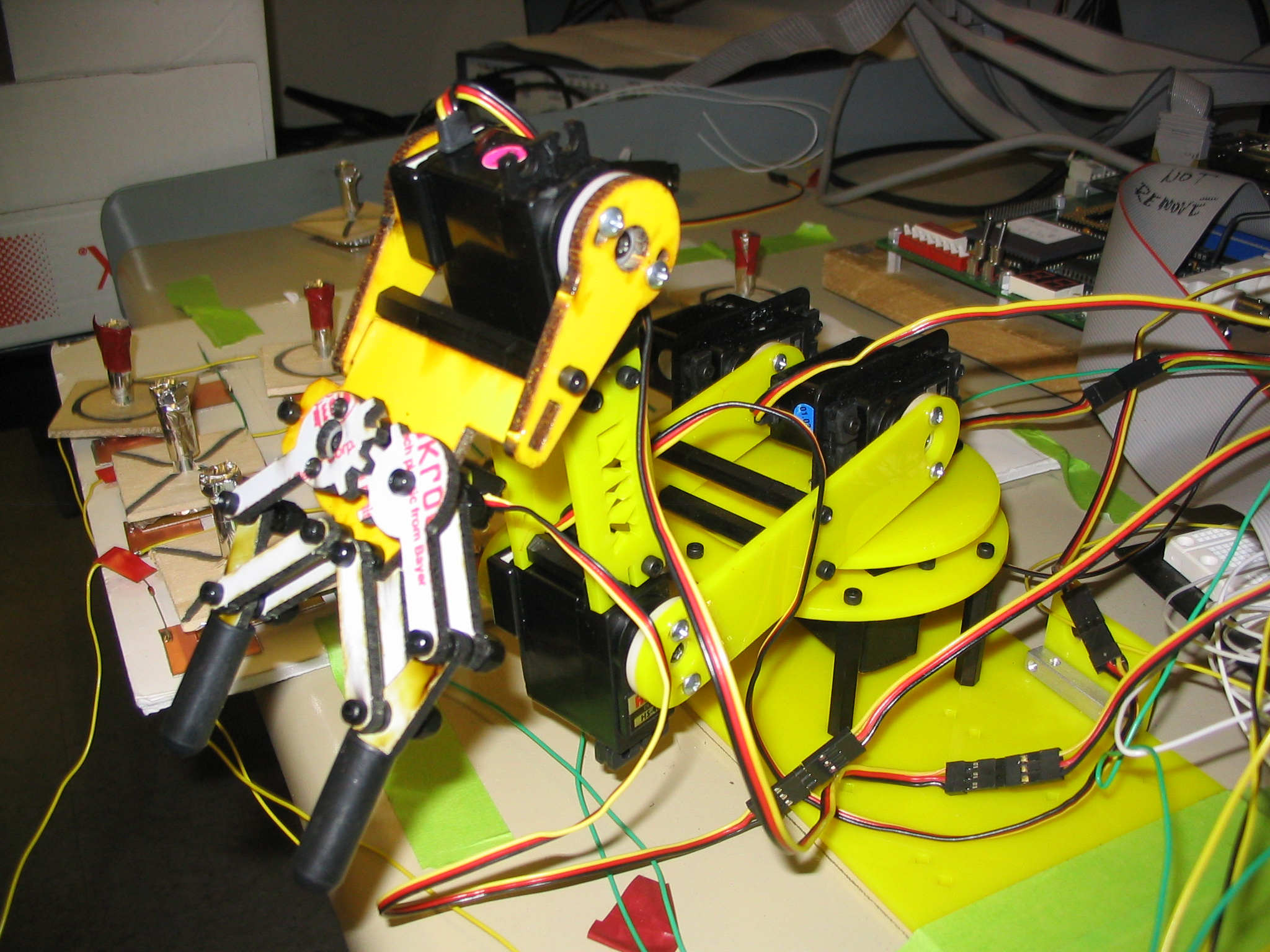
Robotic Arm
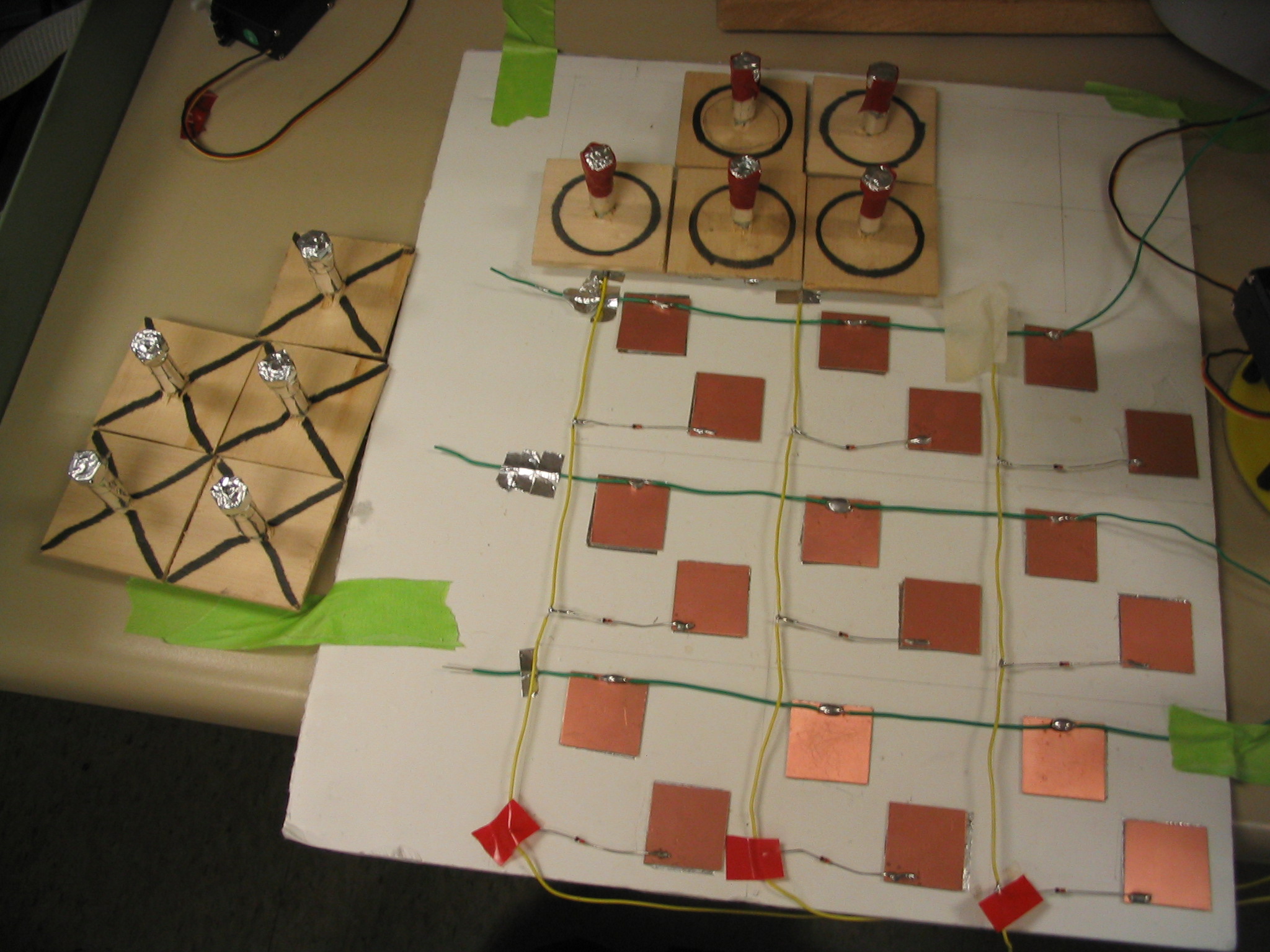
Board and Pieces
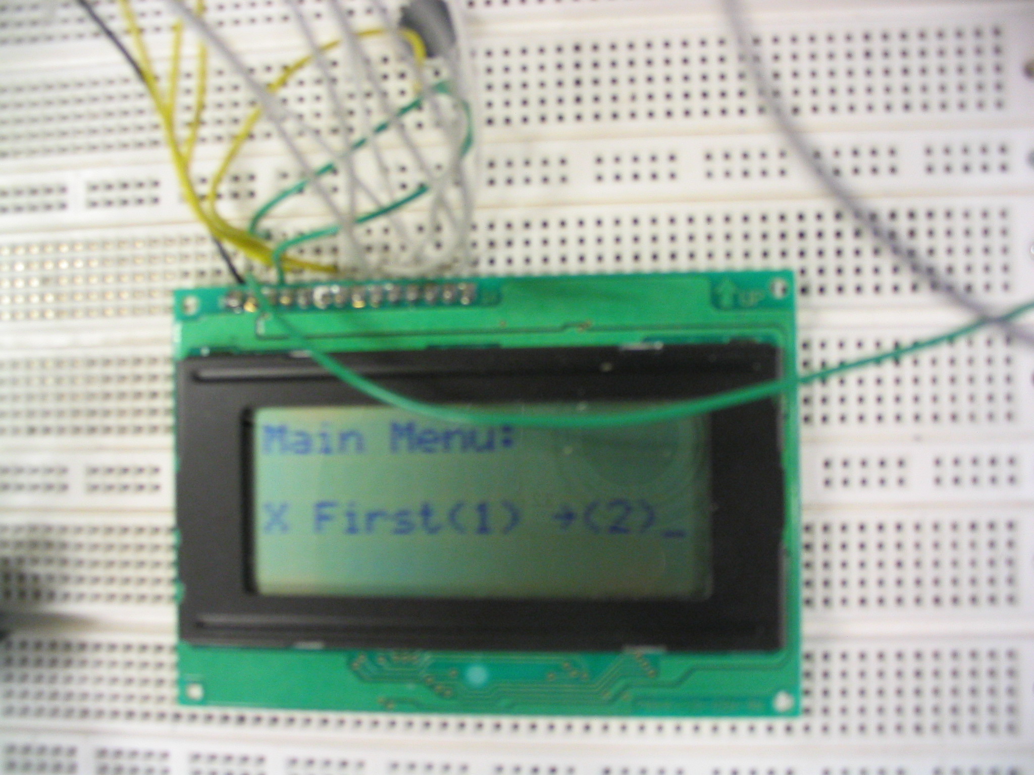
LCD

Click the claw to watch a game.
In conclusion, we were very happy with our final design. We were able to play multiple games of Tic-Tac-Toe, without problem. All in all we did everything we set out to do, and the claw worked as well as we could have imagined.
If we had more time to work on the project, we would have gotten a replacement servo for the micro servo on the claw, and improved on our algorithm for piece placement. As it stands, the claw can still lose on hard difficulty if the user makes certain moves. It would not be very hard to fix so that the claw never lost, but we ran out of time.
Other than those two small changes, we wouldn’t do anything different next time. We both learned a great deal about interfacing with external hardware, and were very pleased with our results.