Inverse Pendulum Robot
Jeffrey Rogers - Jake McCrary - Ivan Wong
University of Michigan - EECS 373 - Winter 2006
Jeffrey Rogers - Jake McCrary - Ivan Wong
University of Michigan - EECS 373 - Winter 2006
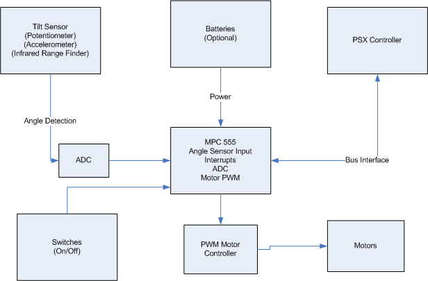
The Inverse Pendulum Robot is an unstable system that balances itself by driving under its own calculated center of gravity. The center is determined by the use of a potentiometer which serves as an angle sensor, and a Proportional Integral Differential control algorithm determines the torque of the motors. Using a PSX controller, we can trick the robot into believing its center of gravity is elsewhere and thus persuade it to move forward or backward.
The idea is reminiscent of a Segway, which is something like a glorified self-propelled scooter that, although unstable, does not fall down. The Segway scooter is an application of the inverse pendulum problem. The goal was to reproduce, with a limited capability, a scaled-down version of this. The idea was that we could make a two wheeled robot that could solve this complex mechanical problem. We further expanded on the idea by adding the ability to wirelessly control it.
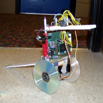
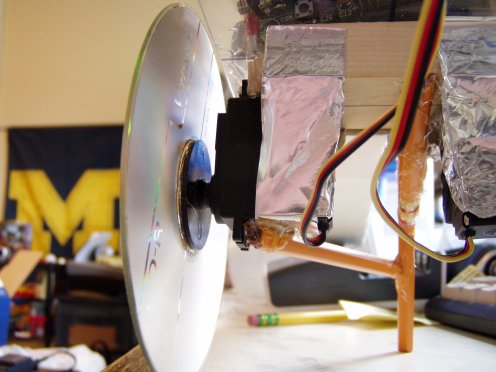
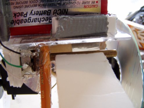
The robot was designed such that balancing would be a non trivial task. We did this by giving it a center of gravity higher than its wheel axis. We modified the rc servos for continuous rotation, and mounted them to a piece of wood.
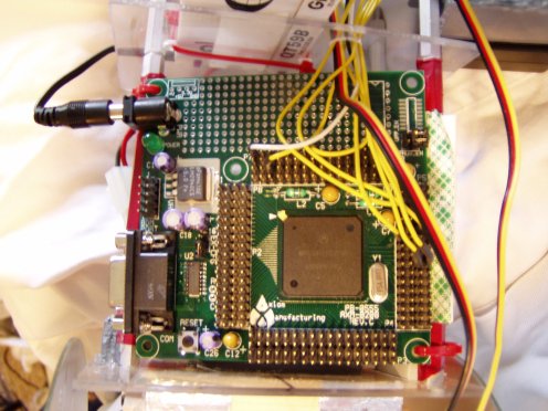
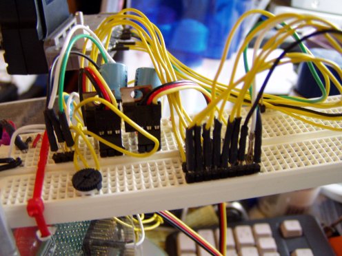
Attached to the wood is a system of plexiglass decks. The decks were made to be reconfiguarable in order to make mounting components easier. The microcontroller and battery were mounted on the first deck, and a breadboard was attached to the upper deck for easy circuit prototyping.
Underneath the first deck, near the rc servos, the linear potentiometer was attached. A piece of foam board is attached to the pot arm so that it can rotate in relation to the ground. Pencils were used to prevent the robot from falling backwards when the balancing routine is disabled. The pencils have no effect on the robot's ability to balance.
Thanks to codewarrior and the mpc555 header files, we were able to write most of our project in C. The only assembly required was our __start routine and the interrupt service routine. The interrupt service routine was adapted from a previous mpc555 project, simply to save time.
At the heart of our software is the balancing routine. It consists of a Proportional Integral Differential, or PID, control system. The PID control system takes in the robot's angular error and outputs torque values for the motors. The output torque is equal to the sum of the error, the first derivative of the error, and the integral of the error. Each term in the summation is weighted by a constant.
torque = 7 * error + 3 * error_rate + 4 * integral;
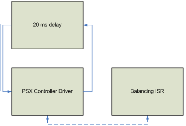
The derivative helps to reduce oscillation in the system, and the integral helps to overcome nonresponsiveness in the motors. The balancing routine is executed 25 times a second, triggered by the PIT. Accurate timing is necessary for the integral and derivative to be computed.
The playstation controller driver runs in the main body of the code, about every 20ms. Since the protocol is syncronous, it is not disturbed by the balance interrupt routine. The driver is essentially a programmed I/O implementation of the SPI protocol. The routines were modeled after the linux PSX controller module, gamecon.c. They required significant modification, though, in order to use the GPIO of the MPC555, achive ideal timing, and to force the playstation controller into analog joystick mode.
The balancing routine uses the playstation controller data to influence the behavior of the robot. Rotational control is achieved by adding the x-axis joystick value to one motor's torque and subtracting it from the other motor's torque. Transversal control is achieved by adding the y-axis joystick value to the angular error fed into the PID.

The protocol works much like many of the I/O buses that we have already worked with. In fact, it is almost identical to SPI, a common serial protocol. The controller has two uni-directional single bit buses, one for the controller to the system, called DATA, and the other for the system to the controller, called COMMAND. A CLOCK signal, generated by the system, is used to keep things in sync. A fourth signal, ATT (attention), is used by the system to inform the controller to listen for commands. The last signal, ACK (acknowledged), is used by the controller to inform the system that communication is established. .
Data is transfered in 8 bit chunks. Each bit on the DATA and COMMAND buses are set up on the falling edge of CLOCK, and sampled on the rising edge. The clock has a 50% duty cycle with 8us period. After the 8 bits are sent, the controller will pull ACK low for about 2-4us. After ACK goes high again, the next bit is sent. In practice, ACK can be completely ignored.
The protocol is simple: First, the system pulls the ATT signal low to get the attention of the controller. This signal is held low for the entire duration of the transaction. About 50us later, the system sends the controller a start command which, like all commands, is one byte. The 8 bit start command is 0x01. Next, the system will send a request data command of 0x42, and at the same time the controller will respond with its ID, dependent on its mode of operation. next, the command bus will go idle (0x00), and the controller will send 0x5a, signifying that everything is ok. If the controller is in analog mode, id = 0x73, then for the next 6 bytes, joystick and button information is sent. After these 6 bytes, ATT is brought back high.
Just in case you are wondering, here is the poorly documented command sequence to force the controller into analog mode.
Forcing the controller into analog mode:
Packet 1: {0x01, 0x43, 0x00, 0x01, 0x00, 0x00, 0x00, 0x00, 0x00} - enter config mode
Packet 2: {0x01, 0x44, 0x00, 0x01, 0x03, 0x00, 0x00, 0x00, 0x00} - set to analog mode and lock the mode
Packet 3: {0x01, 0x43, 0x00, 0x00, 0x00, 0x00, 0x00, 0x00, 0x00} - exit config mode
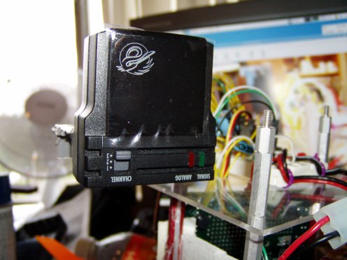
One of the complications we encountered was interfacing with the Logitech Wireless Playstation Dual Shock Analog controller. Although we were communicating with the receiver, we weren't getting any information from the controller. In an attempt to solve this problem, we wrote a few undocumented commands to the controller. A few initial attempts of this made our regular wired controller misbehave, and had no result on the logitech controller. Once we perfected our extra commands, we were able to force the controllers into analog mode, and suprisingly make the wireless logitech controller vibrate, but we were still not able to get data back from the wireless controller. To tempt us to go insane, the wireless logitech controller spontaneously worked for a half hour period, until the robot fell over and reset. We speculated that the controller required very strict timing to interface with, and so we ended up switching to a different, crappier (and therefore easier to interface) wireless controller.
Another problem we encountered was with the rc servo motors. They were high enough torque, but they just weren't peppy enough. We tried to regear them, but as a result they didn't have enough torque to turn themselves. We dealt with the problem by going with the original gear ratio and switching to larger, shinier, compact disk based wheel. Switching to CD's required us to remount the motors slightly further out, so we added metal tape to help keep things rigid. As a result, we had a faster, more blingified robot.
It is certainly possible to implement an inverse pendulum robot with the components we used. It is important to note, however, that the hardware components we used were barely adequate. The rc servos, although high in torque, were rather slow, and as a result we had a very narrow balance window. In addition, the linear potentiometer we used had a much larger travel than desired, which effectively reduced the resolution of the angle measurement. The MPC555 was more than adequate for our 25 hertz balancing routine, and the included hardware components came in handy. If we were to do this project again, we would have sought out peppier servos and a smaller travel pot.
 Video 1
In this video, you get to see that the robot truly can balance!
Video 2
In this video, you can see the PSX controller in action.
Video 3
This is a prettier video of the robot balancing.