University of Michigan Winter 2007
Come with me if you want to live.
Kevin Blasko - Nick Quinnell
University of Michigan Winter 2007
Come with me if you want to live.
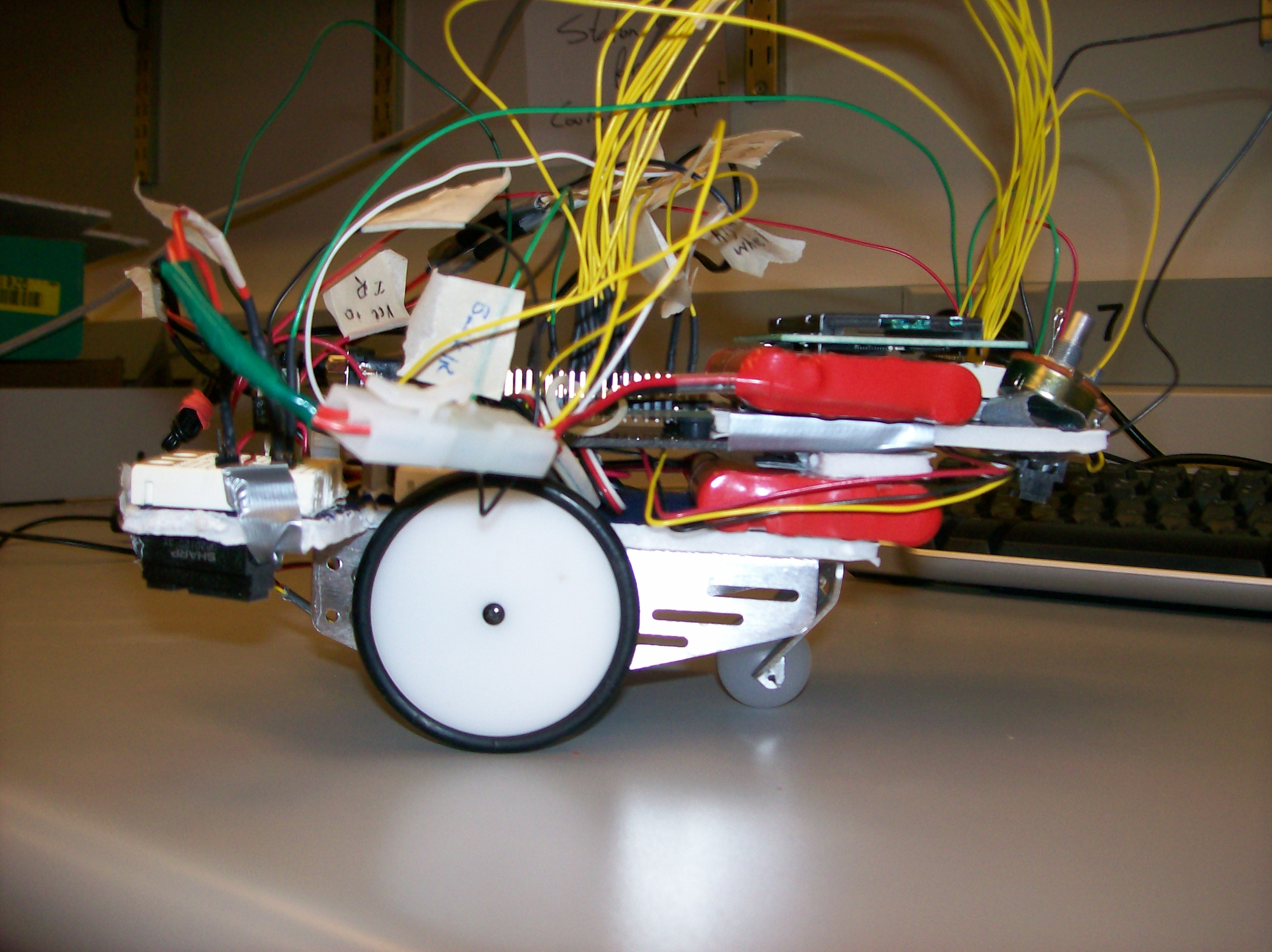
The idea for this project is a mix of an original idea that we had with some input from Mark Brehob and Matt Smith. The project's main goal was to construct an automated car that could be set down on table and drive itself. The interesting part is that the car would never fall off the table. So collectively it was decided that the car would use some kind of sensor (either IR or ultrasonic) to detect the edge of the table and take the appropriate action at that point. We also planned to add some sensors on the front of the car for object avoidance and a character display to let an observer know what the car is doing.
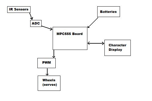
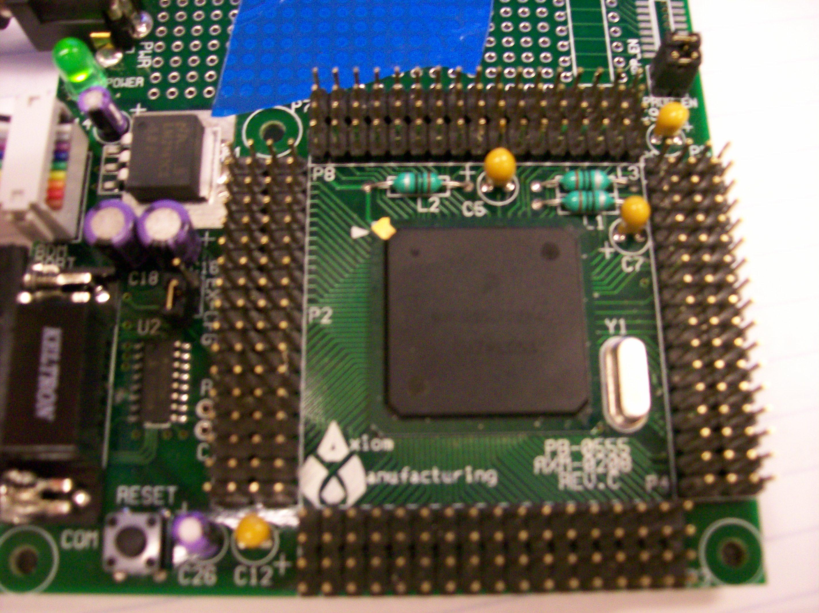
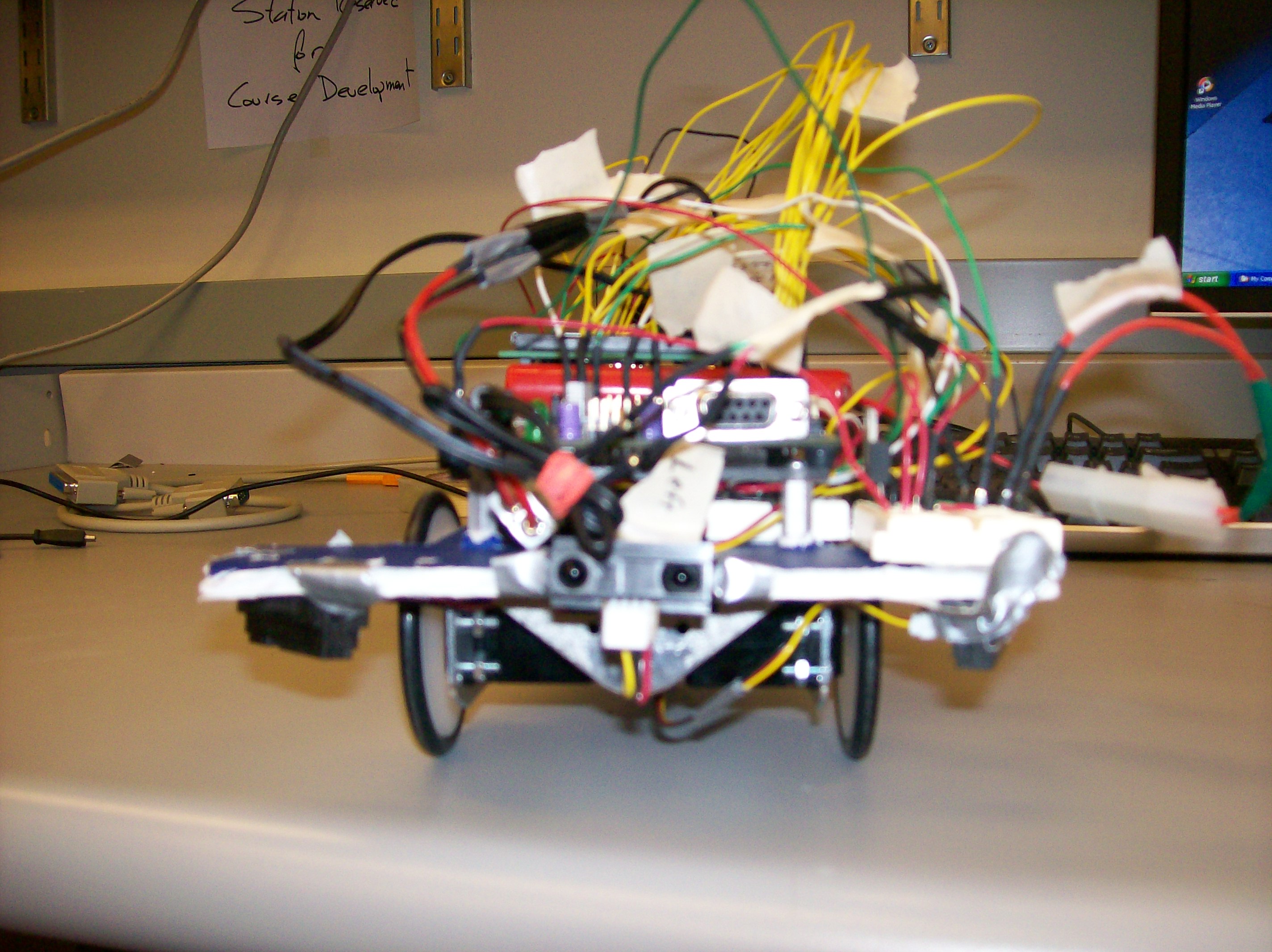
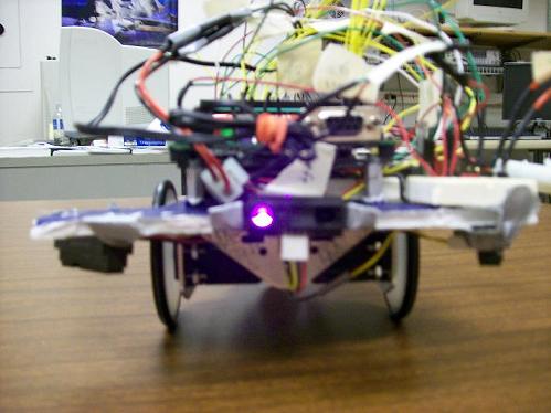
Concerning the IR sensors, our implementation did not require us to find an object a specific distance away, so this part of the project wound up being a little ad-hoc. We set the car down on a surface, tested the output from the IR sensors, then gave this value an upper and lower bound. From this range we were able to determine when the IR sensor was over the surface the car was on and then it was hanging over the edge of the table. A similar process was involved with the IR sensor on the front of the car. In this case we made the range for when an object was between one and two inches in front of the car. The algorithm that responds to the values from the IR sensors is pretty simple. It's main structure is a while(1) loop that checks each sensor. If the left sensor's value is out of range, then stop - back up - turn right. There is obviously an routine for the right sensor. If at any time during the 'back up' or 'turn' state the rear IR sensor went out of range, the car would stop and attempt forward motion again to distance itself from the edge. In all, the car consisted of 4 IR sensors, the 555 board, a 'bobot,' two batteries, and a character display. The 'bobot' was a metal frame with three wheels, two of which were controlled by servos with the third being uncontrollable.
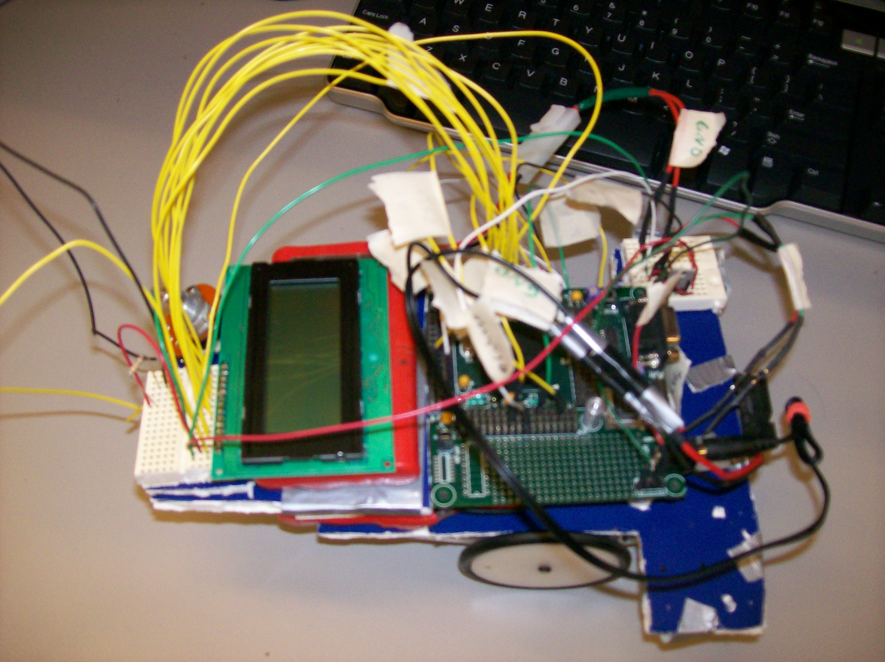
The easier part of the design was actually building the car. It consisted of cutting a piece of foamboard that was mounted to the body of the bobot. On this, we attached the left, right, and front IR sensors as wells as the battery pack that powered the mpc555 board and a piece of breadboard that was used for supplying power to the wheel servos. Using standoff screws, we attached a small piece of plexiglass above the foamboard, and to this we attached the actual 555 board as well as another battery pack (this one to power the wheels), the character display, and a small piece of breadboard that provided the interface to the character display.
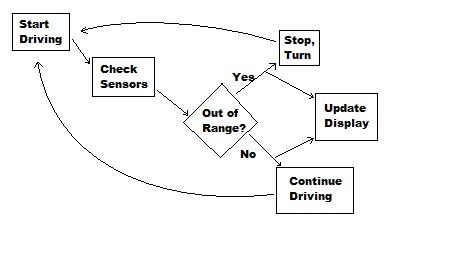
Because the mpc555 does not use an FPGA, almost all of our design is contained in software. Because of the nature of CodeWarrior, we did not have to implement any functions in assembly. If we had used interrupts, however, some assembly would have been required for the interrupt routines. The main part of the software is the driving algorithm. It consists of a check for both front sensors to 'see' the edge of the table and checking the single IR sensor pointing forward for object avoidance. If either table sensor is out of range, the car stops, moves backwards, and turns appropriately before continuing to drive. It does the same thing for an object coming into range for forward sensor. However, we periodically check during the backing up and turning stages the rear of the car to make sure it doesn't back off of its driving surface. If the rear sensor should go out of range, the car will stop moving altogether, and attempt to move forward again. If the rear sensor and any of the sensors on the front of the car are 'bad,' the car will go into its "I can't go anywhere" mode and display a message appropriately. When the car changes its state (from moving forward to avoiding something or vice versa) it will update the character display to let an observer know why the car is moving in its current manner.
The biggest problem implementing our design was getting the software to work. In the end, almost everything worked the way we expected, but we had to get over the initial hump of using new development tools and a new microprocessor. We had originally planned to use the IR sensors to trigger interrupts, but because of time constraints we chose to use a polling method instead. However, this did not compromise the functionality of our design. We also had to implement a work-around for using the character display. Since we did not have an FPGA, we used empty for-loops to create a timing scenario for writing to the display. In the end, there were no unresolved problems with our design.
Our project was by no means impossible, and given more time, interrupts could have been implemented as well. It is also likely that given more time we could have ran our program from the on-board flash instead of from the internal SRAM. The mpc555 was more than enough processing power for what we wanted to do. If we could do things differently, it would consist of the following:
Motorola PowerPC 555 and You (.doc)
Motorola PowerPC 555 and You (.pdf)
General Purpose IO
Queued Analog to Digital Converter
Pulse Width Modulation
Flash Programmer Settings
MPC 555 White Book
Pin mappings for the PB555 Be sure to check the second page as it contains the most useful information.
Manual for PB-555