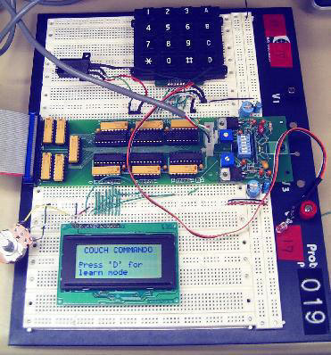
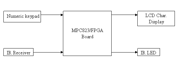
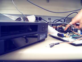
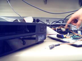
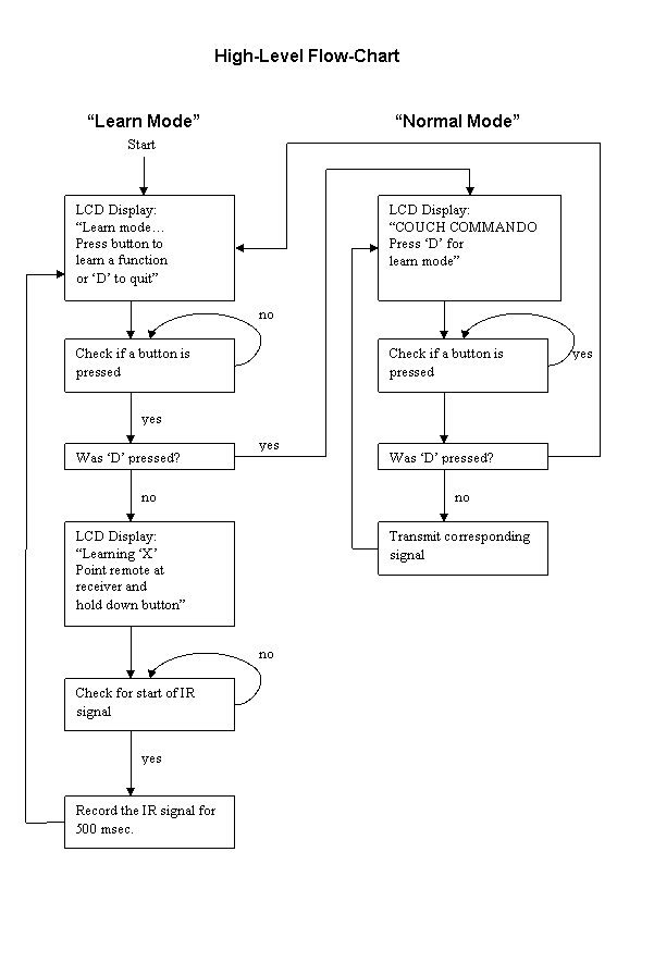
Couch Commando

Universal Learning Remote Control

Members:

Greg Andrzejewski                             andrzg

Jou-ching (George) Sung                    jouching


Introduction:

Even a modest home theater setup may require one to fumble with a stack of remote controls, each controlling a specific component. Most of these remote controls work by toggling an infrared LED on and off in a specific pattern. By sampling these patterns and then transmitting with our own IR LED, we can duplicate the functionality of many remotes with a single device.


High Level Design

Member Task Distribution

Hardware Design

Software Design

Results

Conclusion


High Level Design:

A numeric keypad and LCD character display is used for I/O with the user. The LCD character display provides simple operation instructions. To adequately capture the signal emitted by a remote control, we rapidly sample for the presence of IR light and store these samples in the MPC823’s memory. A button on the keypad is designated that when pressed, these samples are used to toggle an IR LED on and off, thus replicating behavior of the original remote control.


Member Task Distribution:

George:

  • Designed hardware for interfacing the numeric keypad.
  • Wrote the device driver for the numeric keypad
  • Designed hardware for interfacing the IR transmitter and receiver.
  • Wrote the device driver for the IR transmitter and receiver.
  • Wrote the software code that integrates the IR transmitter/receiver with the numeric keypad (UI).


Greg:

  • Initial theory of operation
  • Implement bi-directional data bus
  • Interface to LCD Character Display
  • Wrote LCD Character Display device driver (clearing display, display string, etc.)
  • Assisted in hardware design for keypad and IR transmitter/receiver
  • Assisted UI development


Hardware Design:

The functions implemented in hardware include interfacing the numeric keypad, sending/receiving infrared signal data from the IR transmitter/receiver, and interfacing the LCD character display.


Interfacing the numeric keypad:

Our hardware provides a method to determine which keys are pressed on the numeric keypad. We allow the processor to apply logical 1’s and 0’s to the columns, and to read from the rows. By successively applying a logical 1 to each column one at a time, and reading from the rows each time, the entire numeric keypad matrix can be scanned.


Sending/receiving infrared signal data from the IR transmitter/receiver:

We allow the processor to read from the IR receiver and write to the IR transmitter at any point in time. Our IR receiver, a Panasonic PNA4602M, already has a 38 kHz filter built into it. While limiting us to remote controls using a 38 kHz carrier frequency, digital signals coming from the IR receiver do not need additional signal processing.


However, to write to the IR transmitter, we had to AND the digital signal coming from the processor with a 38 kHz clock, in order to provide the required 38 kHz carrier. The 38 kHz clock was created by diving the main bus clock (which is set at 10 MHz), using an FSM clock divider created in Verilog. If no signal is being written to the transmitter, the transmitter continues to transmit its previous value. That way, we ensure that the signal we transmit is stable and valid.


Interfacing to the LCD character display:

The LCD character display driven by the HD44780 display processor. The HD44780 simplifies text display by providing preprogrammed ASCII characters and symbols. The HD44780 is interfaced to our project using an 8-bit bi-directional bus. Setup and hold times of various signal lines are met using the same array of flip-flops technique used throughout the semester. Once an initialization routine performed, the display is ready. All commands are sent to the display after ensuring that the HD44780 is not busy.


Software Design:


On a lower level, our software consisted of device drivers for the numeric keypad, the IR receiver/transmitter, and the LCD character display


On a higher level, our software integrated the functionalities of the numeric keypad, IR receiver/transmitter, and LCD character display.


Device driver for the numeric keypad:

The device driver for the numeric keypad returns the state of each of the 16 buttons on the numeric keypad at any given moment. As previously described, in order to scan the numeric keypad, our software successively applies logical 1’s to each column one at a time, and reads from the rows each time a ‘1’ is applied to a column. By doing so, our software is able to determine which buttons are currently pressed or not pressed.


Device drivers for the IR receiver/transmitter:

The device drivers for the IR receiver/transmitter allow other components of our software to easily read/write digital values from/to the IR receiver/transmitter. Note that the signal coming from the IR receiver is an inverted signal.


Device driver for the LCD character display:

The device driver for the LCD character display consolidates all necessary steps for accomplishing a task with the HD44780 into individual ABI-compliant functions. This greatly simplified writing higher level software, as we didn’t need to concern ourselves with checking the busy flag, looking up opcodes, or any  housekeeping tasks with the display. We could just call a function that would take care of everything and return with the task finished.


Overall software design:

Since our remote control operates in two modes, our overall software is separated into two categories: Learn Mode and Normal Mode.

Learn Mode:

The general functionality of Learn Mode is to map a certain button on our numeric keypad to a function on any remote control. Each of the 16 buttons on the numeric keypad has its own section of memory allocated to it (we allocate 2048 bytes per button). This is used to store the recorded IR signal corresponding to each numeric keypad button.


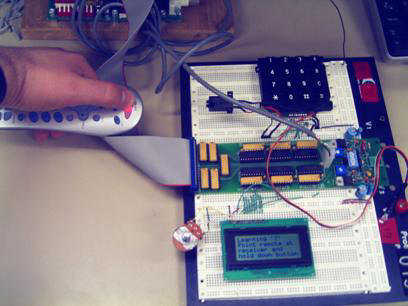
When we first start Learn Mode, we use the LCD display to instruct the user to press the button on the numeric keypad that he wishes to map. Our software continuously checks the numeric keypad to determine if the user has pressed a button. We scan the numeric keypad matrix at a rate of 25Hz. This sampling rate is accomplished via timers that throw interrupts every 1/25 seconds. The corresponding ISR will first determine the state of the 16 buttons, and then write that state into a global variable so that our other functions will be able to access the data. If the button ‘D’ is pressed, our software will go into Normal Mode.


After our software knows which button the user wishes to map, our software uses the LCD display to instruct the user to point the remote at the IR receiver and press a button on the remote. The button that the user presses will be the functionality that our Universal Remote will learn. To detect whether the user has pressed a button on his remote, our software waits for the falling edge of the signal coming from our IR receiver (remember the signal coming from the IR receiver is an inverted signal). To detect for the falling edge, our software goes into a loop that continuously reads from the IR receiver and checks for a logical ‘0’.


Once the falling edge of the signal is detected, our software begins to record the signal. We sample the incoming signal at 4000Hz, so we have configured a timer to throw an interrupt every 1/4000 seconds. During each of those interrupts, the ISR simply reads from the IR receiver and stores the data in the appropriate place in memory. We wish to sample for 500 milliseconds, so that translates into 2000 samples. Once we have obtained 2000 samples of the incoming signal, we stop the timer and mask out its interrupts.


Once the recording is complete, we return to the first state of Learn Mode.


Normal Mode:

The general functionality of Normal Mode is to transmit the recorded signal of a button when the user presses that button. It operates like a normal remote control in this mode.


Normal Mode begins by using the LCD display to tell the user to press the button that he has mapped. Similar to Learn Mode, our software uses timers and interrupts to detect for button presses on the numeric keypad at a rate of 25Hz. If the user presses button ‘D’, our software returns to Learn Mode.


Once a button press (not ‘D’) has been detected, our software determines the appropriate place in memory to fetch the corresponding signal data. Then, we transmit our recorded signal via our IR transmitter at a rate of 4000Hz. To obtain this 4000Hz rate, we use timers and interrupts, as in Learn Mode. Once we have transmitted 2000 samples of data, we stop the timer and mask out its interrupts. Then we return to the beginning of Normal Mode.

Results:

Our design proved to be very workable. We were able to control devices with the Couch Commando just as if we were using the original remote.  Performance was very consistent. When the Couch Commando worked, it worked; when it didn’t, it didn’t. More specifically, the Couch Commando didn’t always get a good signal sample. Inconsistencies in sampling leads to an unresponsive device.


Conclusions:

Hardware-wise, the Couch Commando performed satisfactory. The problems stemmed from the software not being able to sample from the IR receiver and store the results fast enough. The easy answer is to demand more processing power. The better answer, though, is to implement a more efficient sampling procedure. Rather than sampling the signal amplitude at a given interval, using timers and recording the length of each pulse should yield better accuracy with less demand on system preformance.