Automatic Sentry Cannon
To protect a nation's vital secrets
By Tom Voorheis and Colin Sprinkle
Introduction
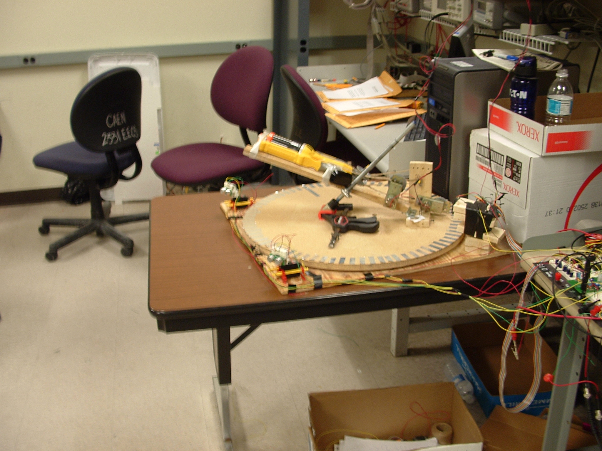
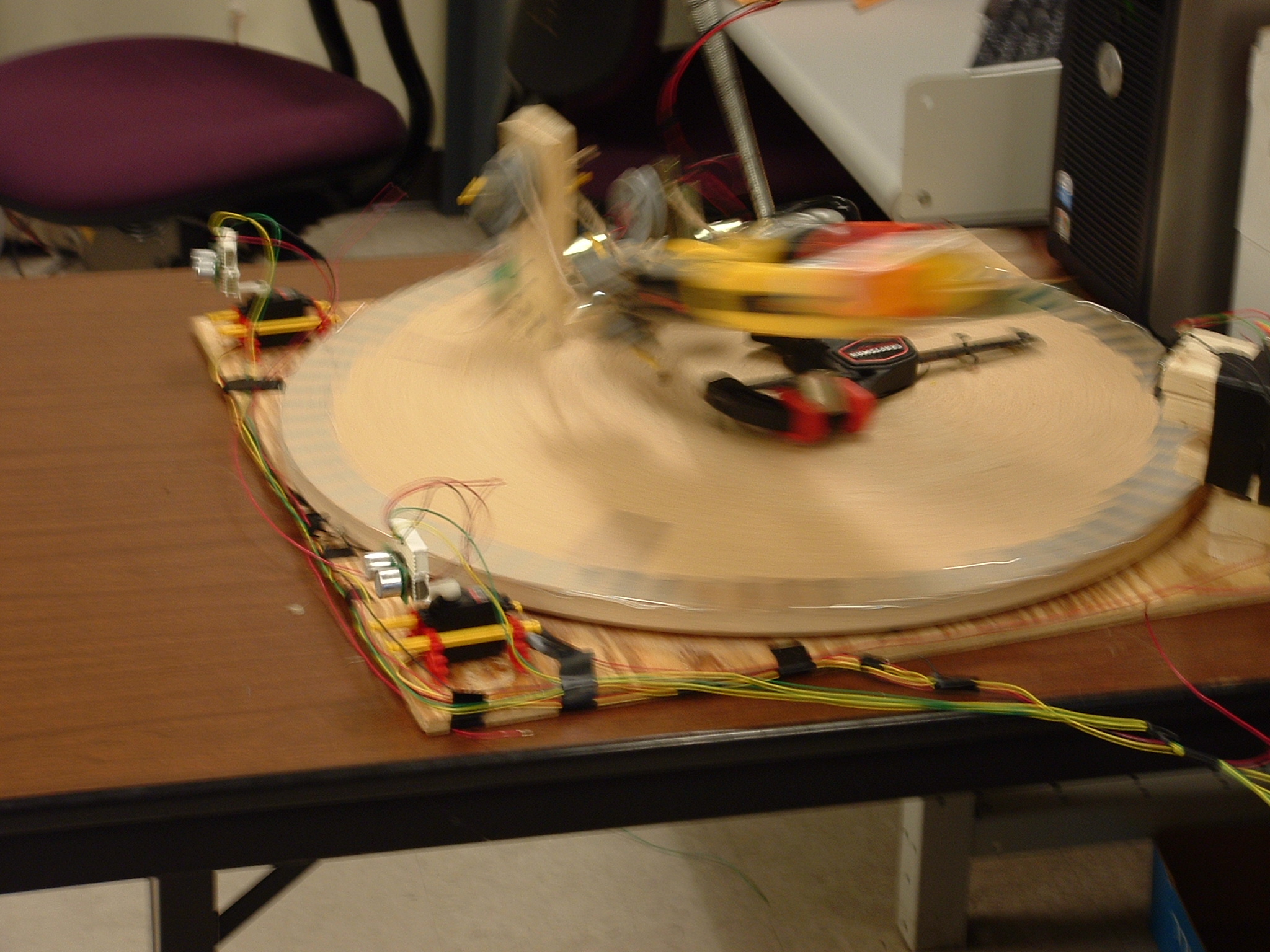
We all know that safes may be cracked, people may be persuaded to divulge secrets, and deep underground military bunkers may be tunneled into with only a few years of backbreaking labor. So what is stopping people from discovering a nation's vital secrets? Until yesterday, nothing. Today, the automatic sentry cannon can take care of all your security needs! The idea of this project is to have a stationary cannon which senses the people and objects around it. Based off of two ultrasonic distance sensors, objects may be detected in front of the cannon. If a person or object gets too close to the sentry cannon, the unit will use motors turn towards said object and fire.
High Level Design
There were several measurement, control and algorithmic concepts employed in this project. There were three main things that needed to be measured: the distance from the left sensor, the distance from the right sensor, and the current position of the cannon. These measurements were taken and processed by the software for use in certain control loops. For example, suppose a distance sensor returned a value of one foot. The software will then determine exactly where the object is based off the current angle of the sensor and the distance the sensor detected. If the cannon is not already pointed in that direction, a control loop will turn the turret until it is facing the correct position. Algorithmically, a three state machine was used. One state is used for scanning, another state is used when tracking, and finally, a state is dedicated to firing.
Member Task Distribution
Tom Voorheis
Tom was mainly responsible for the software portion of the project. This included writing most of the assembly and C code. Tom accordingly designed the algorithm used for tracking targets. Aside from the software, Tom also determined exactly how the distance sensors and servo motors work, and wrote the low level assembly drivers, as well as designing the FPGA Hardware to interface with them.
Colin Sprinkle
Colin was mainly responsible for the hardware side of the project. Colin built all accompanying circuitry needed for the motors, as well as assembling the project and mounting all sensors and motors. Colin also wrote the trigonometry functions in C to determine exactly which direction the gun should be pointing at.
Both
Both of us were responsible creating FPGA hardware for the project. We were also both involved in the debugging of software and hardware related issues. We have both dedicated much time and effort towards the development of this project and therefore the breakdown should be fifty-fifty.
Hardware
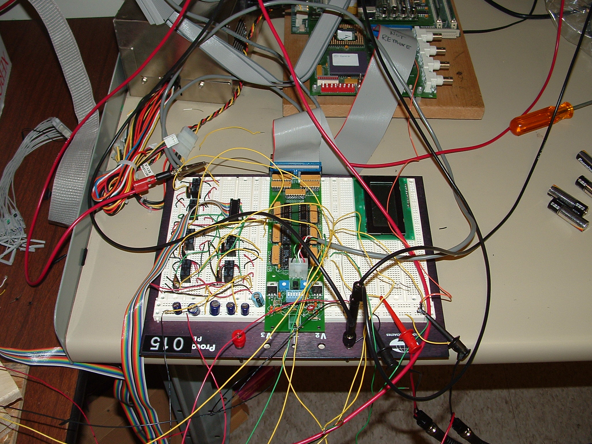
There were several hardware related design issues that were either handled with FPGA hardware, or by special hardware in the processor.
The distance sensors needed a couple hardware components in the FPGA in order to work properly. In order to use the distance sensors, they must receive a pulse with a specified width. This pulse width needs to be precise or the measurements will be inaccurate. Therefore, an FPGA module was built so that when the processor writes to the device's address, a precise pulse is automatically generated in hardware and sent to the appropriate sensor. Receiving data from the ultrasonic detectors is equally challenging. To communicate the distance of an object, a pulse is generated by the sensor and sent to the expansion board. The width of this pulse determines actual distance sensed, thus it is necessary to get an exact timing of the pulse width received. Originally, FPGA hardware was devised to time this pulse however, due to technical issues, another route was pursued. In order to time something on a processor, timing hardware is often required. The simplest way to know when to start and stop the timer is to have an interrupt on the positive and negative edge of the incoming signal. Unfortunately the interrupt controller on board the processor can not be configured to handle both edge transitions. FPGA hardware was built so that a pulse is generated on the rising edge of the signal coming from the distance sensor, and another pulse is generated on the falling edge. These two pulses generate two edge triggered interrupts; one to start the timer, and another to stop the timer.
There were three motors involved in the project, with each one being capable of reversing directions. This means that there must be a minimum of six bits to control all the motors. A memory addressable device was created with the FPGA in order to meet this demand. This device was simplistic in that it simply latched the correct bits off the data bus and held those values until another value was directly written to that memory location. These six bits were then fed into test points, which drove the motor control circuitry situated on the breadboard.
For each motor, two NPN transistors and two relays were used. One relay would be used to control whether or not the motor is on, and the other relay would determine the direction of the relay. Because the test points from the expansion board were not enough to activate the coils inside the relays, NPN transistors were used to provide the necessary current to the relay coils. Because five volts was not enough to turn the motors with sufficient speed or strength, relays were necessary in order to completely isolate high voltage lines with the expansion board.
The last sensor used for the project was an infrared sensor for detecting the current position of the cannon. Seventy-six pieces of tape were put on the edge of the rotating table the cannon was mounted to. When the table is rotating, the infrared sensor will alternate on and off as the tape moves past it. Interfacing this sensor to the processor was straightforward in that it could be directly tied to an IRQ line. The interrupt controller was then configured to trigger on the negative edge of the signal. Because the table only rotates when the rotating motor is on or very recently turned off, the direction of the rotation is known. Using the recorded direction of rotation along with the number of interrupts the IR sensor triggers, the current cannon angle may be determined. A small problem with this sensor was encountered. Originally we had hooked it up directly to an IRQ line, however we noticed that sometimes the sensor would double count pieces of tape. Observing the signal on the oscilloscope allowed us to observe a consistently glitch on the rising and falling edges. It was consistent enough that we solved the problem by implementing FPGA hardware that sampled the signal at a bigger resolution than the size of the glitch.
Software
The software for our project bore much of the weight of the functionality of our project, gave it life so to say. The generation of servo signal generation, processing of distance sensor, Infrared data were all done in software using both timers and interrupts in assembly. The detection, tracking and positioning algorithms were all written in C. The distribution of assembly and C allowed us to first complete the assembly code, and when the time came to write the C it was very easy to interact with all of our devices (with no understanding of assembly even). We were able to overcome over-sampling issues with the distance sensors by implementing drivers which blocked until the results had returned, as well as sampling only one distance sensor at a time.
In our original design we had planned to implement the servo control almost entirely via hardware. We spent a good deal of time attempting to debug the hardware for the servos. Due to time restrictions this plan was ultimately dropped, as result of which the two servo motors were controlled by the same control signal (and thus were always pointing in the same direction.) If the servo hardware had been implemented we would have been able to control them separately, perhaps further improving our object detection. Another result of this change was that we were unable to use our 2nd timer, originally we had intended to have the gun cock itself. However, the pulley system we would have used the time the motor attached to needed to be very accurately tracked by a timer, because if it was not it could very easily rip the gun apart. The driver for the servos was written in assembly and worked similarly to the dc motor in lab 7 with timer based interrupts, basing it's duty cycle on a location in memory which was easily accessed in our C code by a EABI compliant driver function.
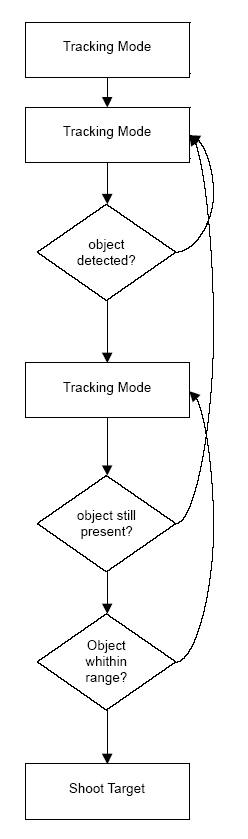
The guns activity was broken into 3 stages, a detection stage, a tracking stage, and a shooting stage. At the beginning of all of the stages 9 samples from the distances sensors from 9 different directions were taken and their median was determined. In the detection stage the distance sensors scanned their entire 180 degree field until an object is detected, once an object is detected the code entered the tracking stage. In the tracking stage the code to determine the position of the object is run and the gun pointed in that direction. The tracking algorithm allows the servos to continue sweeping until the border of the object is reached, at which point their direction is reversed until a second border is found. If an object goes away, and the gun has not been shot the code then returns to detection mode. If the object being tracked enters a certain threshold (for our demonstration this threshold was about a foot from the sensors) the gun would then fire, since we were unable to implement the auto-cocking functionality this is where the software control loop stops. If given more time the control loop could be expanded to include repeatedly firing until a target is eliminated then returning to detection mode, repeating it's behavior. These changes wouldn't require a good deal of effort, the lack of additional timers and difficulty debugging hardware would be the hurdles to overcome.
Flowchart
Results of the Design
As with any large design, there were a number of challenges. The most challenging problem during the entire project was getting both servo motors and distance sensors to work in harmony. After hooking up both ultrasonic sensors and servos, everything stopped working. Although the same control line was being used to drive both the left and right servo motors, the motors did not work in unison. When just one or the other servos were connected, it would work fine. When both servos were connected at the same time, the left sensor would continuously and mysteriously sweep from zero degrees to the correct direction, to zero degrees again while the right servo would stay at zero degrees and jerk severely several times per second. Many things were tried to resolve the situation, until eventually we hooked up the multimeter to the voltage lines of the expansion board. When both servos were connected, the voltage on the expansion board would drop an astounding .2 volts. To resolve this problem, the servos were powered from the larger power supply, revealing the disturbing fact that when the servos were turning, a whopping half an amp was being drawn at five volts.
Alongside technical issues came design issues as well. For instance, the turret was originally designed to sense objects in all directions. Unfortunately, the servos are limited to 180 degrees of motion. Although it would be possible to mount a servo on top of another servo in order to get the desired 360 degree range, we believed this would be a recipe for disaster. Another possibility was to mount a distance sensor on the actual rotating table itself, however that would require the table to be constantly moving, and it would offer a very limited degree of precision due to the layout of reflective tape.
Originally, the cannon was supposed to fire at people up to three feet away. Unfortunately, firing the cannon for distances such as three feet was not possible for several reasons. The first reason is that the distance sensors would sometimes return bogus results. Due to noise in the environment, sometimes the ultra sonic sensors would return low values when no object is present in front of it, and other times, a high value is returned even if an object is directly in front of it. After receiving the distance measurements, the program quantized the measurements into feet for debugging purposes. These numbers were then later used in the trigonometry functions described above. The exact position of distant objects can not be accurately calculated because these already quantized values were being used as inputs to highly quantized lookup tables, and having those resulting numbers eventually being used again in another quantized lookup table, coupled with the fact that the rotating table was accurate within 5 degrees. In short, our cannon could never perform as well as we'd hoped because there was no floating point unit onboard the processor. Even though numbers were treated as two decimal fixed point numbers inside the trigonometry functions, sin and cosine could not be accurately computed, limiting our ability to aim the cannon in the correct position for distant objects.
Originally the cannon was supposed to cock itself before firing. One problem was encountered when it was discovered the motors could not cock the motor, even with a gearbox. This problem was overcome by building a compound pulley which enabled the motor to cock the cannon. However, another technical problem surfaced. With the pulley system it took several seconds to cock the cannon. However, the cock handle had to be returned to its original position before the cannon could actually fire. Due to the variable nature of the motor used to cock the gun, a timer alone could not guarantee the cock handle had returned to its original position. It should've been possible to mount an IR sensor on the actual turn table and have a piece of reflective tape on the cock handle, but considering the short amount of time left on the project, other tasks simply had higher priorities.
There was one unresolved, yet resolved problem worth mentioning. For several hours, there was a problem interfacing the distance sensors to the processor. Interrupts were not being triggered when the distance sensors output their pulse to the processor. However after attaching oscilloscope cables to the appropriate lines, this problem was immediately resolved. Although it was never understood why this was the case, it has been verified that the interrupts to not happen unless the oscilloscope cables are attached to the appropriate wires. The cables may be acting as some sort of filter. Several capacitors were placed instead of the oscilloscope to try to determine if that was the case, however no capacitor seemed to work.
Conclusion
Considering the degree of quantization and the relative simplicity of the tracking algorithm the turret worked well. Clearly reducing the quantization and refining the averaging of the distance sensor data would further improve the behavior. With the components we were using we were able to implement our design to a reasonable level, with more work it would most definitely become even more integrated and efficient. Even with better averaging and tracking algorithms, it still comes down to the fact that the trigonometry functions were highly quantized. Unfortunately we were unable to find any fixed point sin and cosine approximation functions written in C. The lack of these functions inherently put an upper limit on the accuracy of the cannon.
Appendix