Members | Introduction | High Level Design | Member Task Distribution | Hardware | Software | Results | Conclusions | Pictures
Roy Wang
Rahul Ramaswami
Our project started out as a blackjack simulator which would make use of a camera to detect hand motions and interpret them as appropriate motions to deal or raise wage. We wanted to overlay the video stream from the camera with graphics and output the "painted" video onto an LCD screen. Due to time constraints, we had to scale down our project to only using an accelerometer and a pressure sensor to detect hand waving motions and tapping on the table, respectively. Our output consisted a 240x64 pixel LCD display, instead of an LCD monitor.
The accelerometer is an analog device and was used to detect and measure player's hand movements. It worked by outputting a voltage according to the acceleration it underwent. There were three axes on the accelerometer, orthogonal to each other, and we used these axes to determine the direction of the hand motions. However, the z-axis was not working and we had to limit hand movements to a plane.
The pressure sensor was used to detect a tapping motion, much like how a blackjack player would tap on the table to want a card dealt. The pressure sensor acted as a variable resistor and would decrease its resistance with increasing pressure applied on it. When no pressure was applied, resistance was very high.
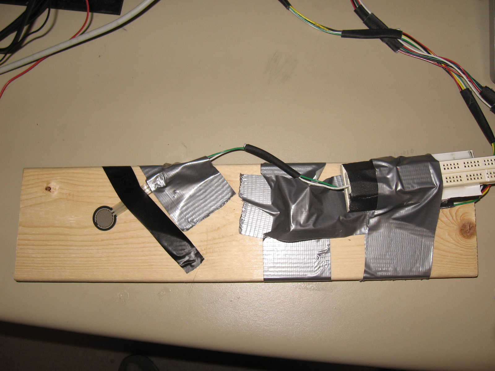
The accelerometer and pressure sensor were meant to be mounted on a real hand, but due to the z-axis not working (hence we could not use the z-axis to reference uprightness) and the looseness of the wire connections, we had to mount both devices on a flat wooden paddle.
The 240x64 pixel LCD display was used as our graphical output. Depending on the motions of the player's hand, the LCD display would output different animations or graphics.
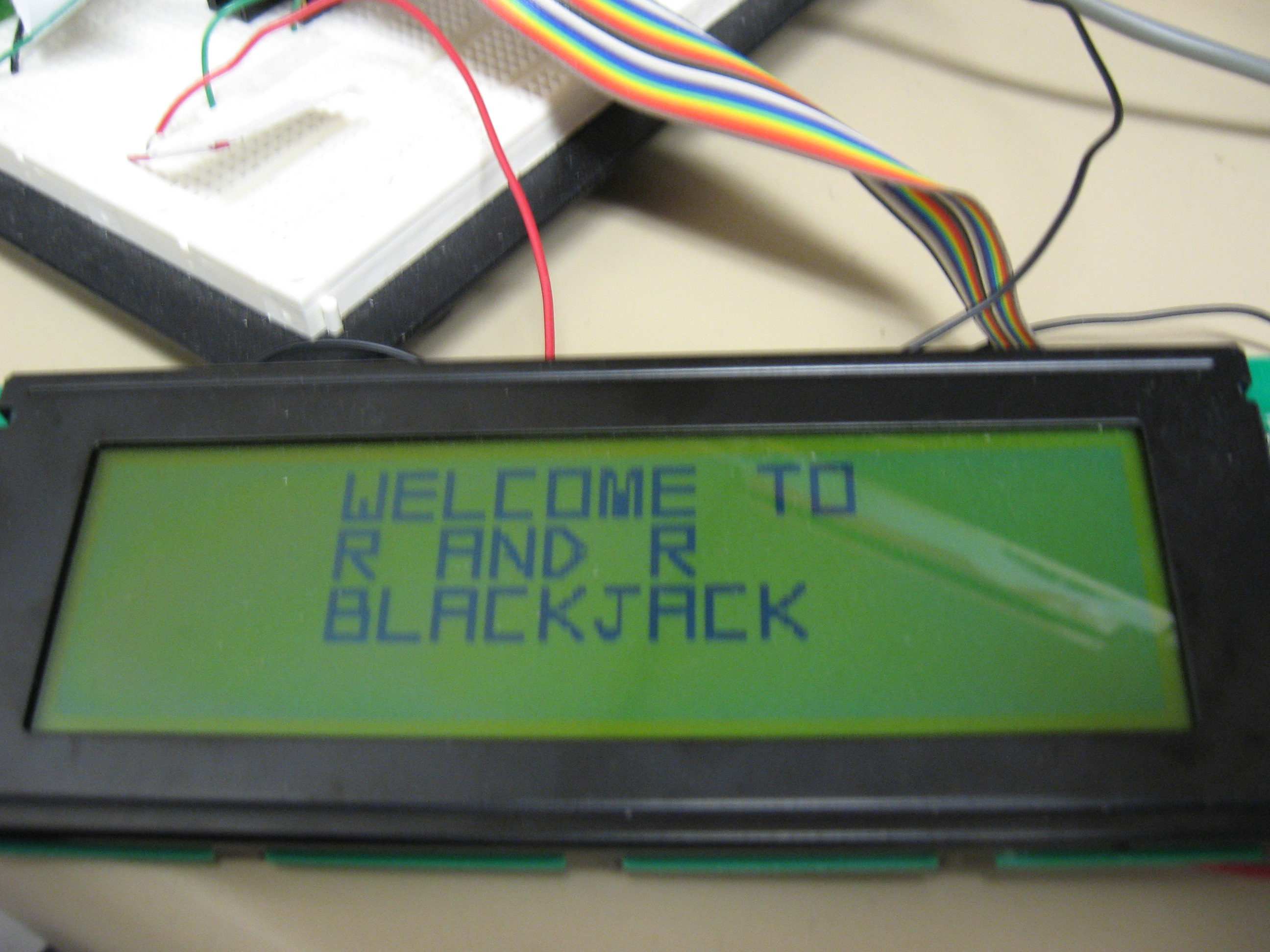
The MPC823 microcontroller acted as the blackjack game. It first started off by displaying a welcome screen on the LCD display, then a tap on the pressure sensor would bring the player to a betting screen. Moving the paddle right would increase the bet by 1, and moving the paddle left would decrease the bet by 1. Tapping on the pressure sensor again would start the actual blackjack game. The MPC823 contained the algorithm for the blackjack game which was adapted from Rahul's EECS 280 blackjack project. When a round was over, the MPC823 would display the bet screen again. Thus, this game would continue until the player quits the game.
Finally, we used one of the switches on the FPGA to alternate between displaying the dealer's and player's cards.
Roy Wang |
Rahul Ramaswami |
| LCD display controls | ADC controls |
| LCD programming -- animation and graphics | Blackjack program |
| Circuit building for pressure sensor and accelerometer | Pressure sensor and accelerometer calibration |
Pressure sensor
Accelerometer
LCD display
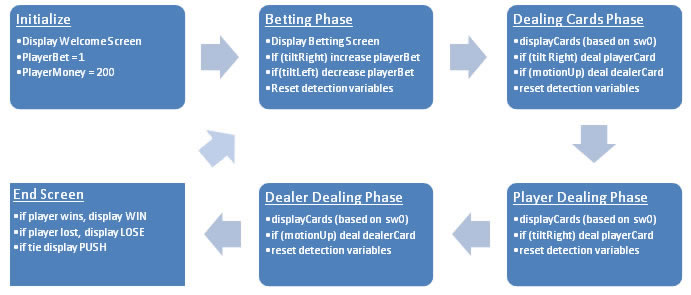
The software is driven by a 20 Hz interrupt. Every time the interrupt is run, it reads the pressure sensor and accelerometer. If it detects anything, it sets global variables based on what it detects. The different global variables it sets are pressure, board tilted right, board tilted left, and board motion up. The blackjack program itself is based on stages. Based on the stage, it does actions after detecting a change in pressure or acceleration. After it’s finished, it resets all the global control variables mentioned above and advances to the next stage. While it is doing an action, interrupts are disabled.
To shuffle the deck, we used the real time clock. In the betting phase at the end of the loop, it shuffles the cards. It sends the value of RTC % 51 into the shuffle function. Based on the randomness of the ADC, it will shuffle the cards for X times each second. X will be different, but the value into the shuffle function will be the same.
The interrupt relied on a polling mechanism once it was called. Because it is only run 20 times a second, we decided it would be the best way to do it. After it writes the ADC mux, it polls the ADC_EOC until that transition from L->H. Once that happens, it reads the value and moves on. The interrupt itself runs of the timer on the MPC hardware. The reason we choose that is because we already had a strong grip about how the timer works and it reduces complexity of the system.
The assembly code contained code to write the ADC mux, read ADC, read RTC value,
A large portion on the software was dedicated to manipulating the graphics on the LCD display. There are functions to draw various shapes and large fonts on the LCD screen simply by inputting coordinates and the graphic type.
The following is the software flow diagram:
We had originally intended to implement a full 3-D detection of hand movements using the accelerometer, but it came to us with the z-axis not responding. As a result, we had to "anchor" the accelerometer to a flat surface to ensure that we were guaranteed a horizontal plane of motion.
Also, we were getting erratic readings from the accelerometer and pressure sensor initially, and then we realised that the wire connections were not robust enough to withstand unrestricted movement. We used pieces of breadboard to connect the two devices to wires, and the breadboard pieces turned out to have poor contacts with the wires. Whenever we moved the devices too fast or turned them around too much, the wires would lose contact with the metal strips in the breadboard. To circumvent this problem, we had to tape down the wires very tightly, and finally taped the devices down to a flat paddle.
Our design needed several different power sources: 3.3V, 5V, 10V, -10V, and -12V. To get around this, we built a "power circuit" to supply different power voltages, essentially using voltage dividers. Since the expansion board also had its own power source, we moved the -12V power source (to power the LCD contrast) to the expansion board, as we could easily adjust the voltage to adjust the contrast of the LCD.
Our blackjack program also needed a random number generator to "shuffle" the cards, and most such programs require a "seed". Typically, a "seed" would be tied to the system clock. Since there was no real system clock on the MPC823. we used a timer to generate a random number. Each time we had to wait for the dealer or player to deal a card, the timer would be running. Since the waiting time is dependent on human input, the waiting time is thus a suitably random number and we used this number to "shuffle" our cards.
Our blackjack program worked as intended in the software. We had all the features we had originally planned implemented. Given all the components we had, we can implements about everything we wanted, except of course the overlay of the world. If we had more time, we could have implemented more advanced actions. Instead of just relying on four actions, we could have had more. With the accelerometer, for example, we could have detected a motion going from left to right. What happens is that the voltage first goes high then as you stop the board, it goes low. We could have implemented a timer to detect if this happens (after it detects a high voltage, 100ms later it polls again and sees if it's a low voltage). Since we know how the LCD works now, we could have spent more time figuring out how the camera worked. If we got the camera working, we could have just used a camera and pressure sensor to get inputs.
Player card being dealt:
Dealer card being dealt:
"Win" animation:
The Paddle:
Welcome screen:
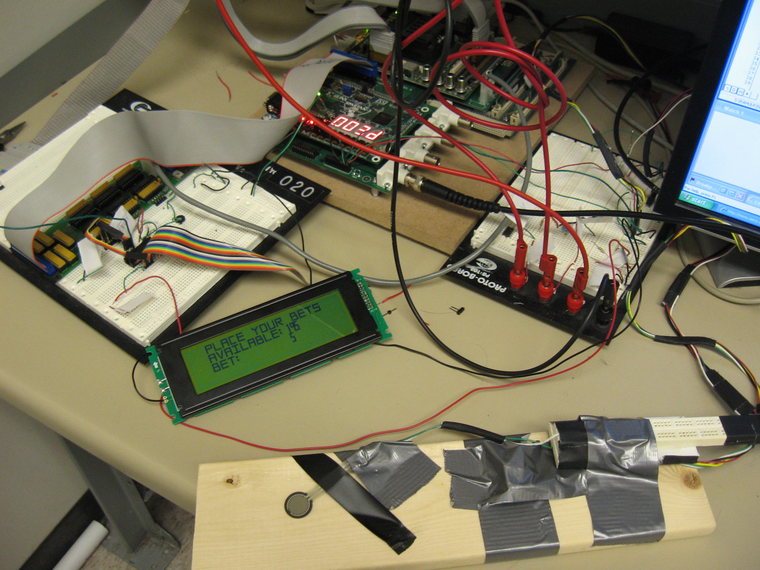
Our setup:
 Blackjack Simulator