Engibeering - Automated Kegerator
Home | Design | Media | Results | References
Design Levels
High Level Design
Hardware Design
Software Design
High Level Design
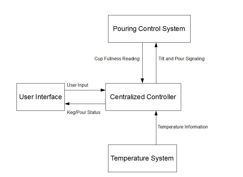
The Automated Kegerator is built from several subsystems whose interactions and function are described below.
Centralized Controller – Based in software, this subsystem transfers information and instructions between the other subsystems. User requests and keg status information are stored and sent to their appropriate subsystems. The centralized controller also translates all timers and sensors, including pour control, temperature sensors and pressure sensors.
User Interface – Consists of the Display and User Control systems. Information about the current keg and its environment can be viewed from a display. Users can interact with the Kegerator via a Nintendo 8 controller and a menu system on the display.
Temperature System – This system monitors the temperature inside of the refrigerator and on the surface of the keg.
Pouring Control System – The pouring control system automatically pours the desired amount of beverage into a standard red party cup. With a maximum pour size, the pouring control system will automatically tip the cup to reduce excessive foam.
Hardware Design
There are several hardware components that make up the Automated Kegerator.

Temperature Sensors
The temperature sensors are actually thermistors or resistors that vary in resistance according to its temperature. In our project we used two thermistors; one to measure the ambient temperature of the refrigerator and the other two measure the temperature of the keg itself. In order to get useful data to the analog to digital converter (ADC) the thermistors are connected to a voltage divider circuit.

In this circuit the supplied voltage Vcc is split up depending upon the resistance of X and the resistance of the thermistor. The main objective with the voltage divider circuit is to get a wide range of voltages to be sent to the ADC; this was the reason for using the op amp. To determine the size of the resistor in the circuit we took five different measurements of each thermistor at temperatures ranging from 32 degrees to 45 degrees (the fridges temperature range).
Pressure Sensors
The pressure sensors work in the same manner as the thermistors. As more weight is applied onto the pressure sensor the resistance decreases. The pressure sensors are then hooked up to a voltage divider circuit and an op amp to give a wider voltage range to send to the ADC. In our project we used three pressure sensors to determine the amount of beer that was poured into the cup. When using the pressure sensors however we found that they were difficult to use for a number of reasons. First we found that the pressure sensors will not respond unless the weight is concentrated and centered on the sensor. To solve this problem we first tried using double sided foam tape but this did not work because the tape would absorb some of the weight. Next we tried gluing small washers onto the sensors but again this did not work because some of glue would spread out onto the sides of sensor and would build up in the center of the washer. The final solution was to take a wood doll rod and cut it into small pieces. After we had the pressure sensors working and connected to the ADC we still found that they were still not always consistent. The initial reading by the sensors usually varied but we found that no matter what the sensors initial reading was, the values read by the ADC would decrease at a constant rate so we could calculate how much had been poured by looking at the differences in the readings.
Motor/H-Bridge Setup/Servos
In order to tilt the cup we used a cam to push the cup holder up. Our initial idea was to use a heavy duty servo but after testing we found that the servo did not have enough torque to lift the cup holder; instead we decided to use a gear motor. In order to use the gear motor we used an h-bridge to control the current to the motor. We then just used a timer to control how long power is supplied to the motor. Then because the pressure sensors are thrown off when the cup is tilted we would only tilt for a full cup.
Building the stand and cam
When building the stand for the cup one of our main objectives was to avoid any unnecessary drilling into the refrigerator. We wanted to make sure that the kegerator could be reused once the project was completed. It was then assembled using plywood and 8x1 boards. We ran into some difficulty attaching the cam onto the motor because the plywood would crack and split. Another issue with the cam was that it would wobble or not remain firmly attached to the motor as it spun.
Solenoid
We used a Rain Bird sprinkler solenoid to control the flow of beer from the keg. To turn on the solenoid a 24V AC current had to be applied to the solenoid. To get a 24V AC current we used a furnace transformer to step down a 120V AC current. In order to control when voltage was applied to the solenoid we used a pin from the expansion board as the gate to a transistor. When writing a one to the transistors gate, current was allowed to flow to the transformer and solenoid. After initially connecting the solenoid beer was still able to flow through it, even without power supplied it. This is because we had the solenoid installed backwards.
Speaker
For our project we used the speaker to play a sound every minute during the power hour mode. The speaker was relatively easy to interface to, using a headphone jack one wire connects as the signal wire and another wire acts as a ground wire. The signal wire is then connected to the expansion board and by writing a square wave with a 50-50 duty cycle at different frequencies we were able to duplicate the Mario 1-up sound.
Building the kegerator
Connecting the kegerator was relatively straight forward. Following the directions from the kegerator conversion kit we used a hole saw to drill a hole through the front of the fridge for the tap to sit at. From there it was just a matter of connecting the tubing from the CO2 tank, tap, solenoid, and then to the door. When connecting the tubing we ran into some small plumbing issues where fittings did not quite fit or were leaky.
Software Design
We designed our project to use a majority of C code and as little assembly as possible. As a reference we finished with around 200 lines of assembly and 2,500 lines of C code.

In our assembly code we set up the timers, and used interrupt handlers to set a flag which notified the C program that the Nintendo controller or timers were ready. In our C code, we created an interface for each device and then combined everything in an event driven loop that relied on busy waiting from the Nintendo controller or timers. We chose to use the timer on the processor board because we needed to have second resolution for the temperature sensors and tilt mechanism and we needed hundredth of a second resolution for the temperature sensors. We were all very familiar with the general purpose timer and real time clock from the lab and decided that it would be the easiest to implement, have the correct resolution, and provide decent latency. We did not have many difficulties with the software, but we did send some time designing the interfaces for the devices. Robert Turer and Stephen Hufnagel worked on the software using extreme programming techniques.
Copyright 2008, Engibeering
Stephen Hufnagel, Steve Reddmann, Robert Turer, Lance Tuscany.
Electrical Engineering and Computer Science Department
University of Michigan