Vinyl to MP3 Transcoder
Jason Bornhorst, Jason Sleight, Josh Smith, John Treumuth
Contents
- Introduction
- High Level Design
- Member Task Distribution
- Hardware Design
- USBWiz
- USB Keyboard
- USB Drive / SD Card
- Character Display
- MP3 Encoder Chip
- Record Player
- Servo Motors
- Software Design
- Results of the Design
- Conclusions
- Media
- Appendix
- References
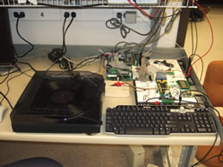
Introduction
For this project, we created a device that would record songs from a vinyl record and convert them to MP3s on a USB drive or SD card. Our device uses a USB keyboard to allow the user to enter album and song names. These names are used to setup the directories and filenames on the storage device. The transcoder uses a character display to relay messages to the user. The transcoder uses an MP3 encoder chip to carry out the conversion. To store files and to interface with the keyboard, our device uses a USBWiz OEM board. To interface with the mechanical controls on the record player, our device uses servo motors to start, stop and pause the music.
High Level Design
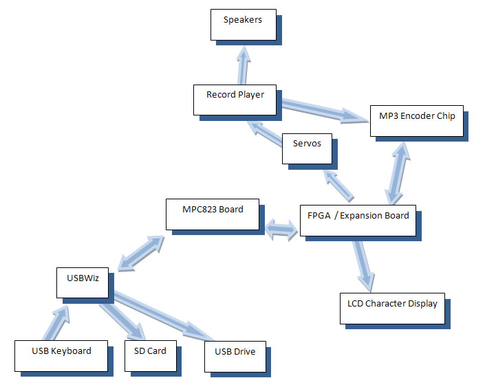
Our device uses the FPGA push-buttons to initiate control of the servo motors that stop, start, and pause the music from the record player. The audio signals are then fed through both the speakers-- so the user can hear the song being recorded -- and simultaneously to the MP3 encoder chip. The same buttons on the FPGA that stop and start the music also send commands to the MPC823 communications module, which then stops and starts the MP3 encoder chip via I2C commands in software. The MP3 encoder chip feeds back 30 byte segments of data to a custom parallel receive buffer on the FPGA. This buffer generates an interrupt when it has recieved all 30 bytes, which causes the MPC823 to store these bytes into an internal buffer we created within the MPC's memory. The main loop of our software is simultaneously writing this internal buffer out to the USB or SD card via the USBWiz, which we interface to through SPI commands in software.
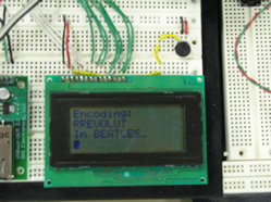
When not recording, the user is prompted to enter song and album names via the USB keyboard, which sets up the file system on the storage device. These prompts are displayed on the LCD display. The user is also prompted to select which type of storage device they would like to use.
Member Task Distribution
Jason Sleight:
USB Drivers
USBWiz Software
SPI Drivers
Display Drivers
Keyboard Software
System Integration
John Treumuth:
USB Drivers
USBWiz Software
SPI Drivers
Display Drivers
Keyboard Software
System Integration
Josh Smith:
MP3 Encoder Chip Hardware/Software
Parallel IO interface
I2C Drivers
Display Hardware
System Integration
Jason Bornhorst:
MP3 Encoder Chip Hardware/Software
Servo Hardware and setup
System Integration
Some debugging of parallel, I2C FPGA hardware
Protoboard setup
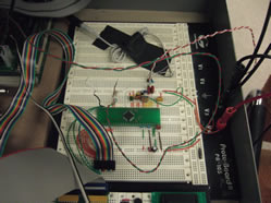
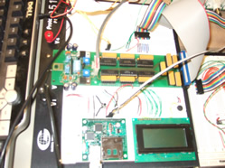
Hardware Design
USBWiz
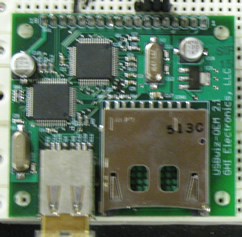
The USBWiz enabled USB drive and SD card storage through SPI communication. It also enabled us to read input from a USB keyboard. Most of the SPI protocol was handled by the MPC823 communications module, but the slave select signal was not. This signal had to be generated through custom FPGA hardware which observed the first SPI clock signal and held the slave select line active for the duration of the transaction. The USBWiz also generated busy and dataready signals which were mapped through the FPGA and were used by our software to control dataflow.
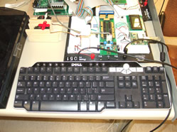
USB Keyboard
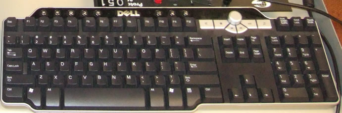
The USB keyboard was used to enter song and album names. Communication with this device was handled through the USBWiz, which transferred relevant information to the MPC823 through SPI.
USB Drive / SD Card
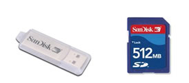
The USB drive and SD Card were used to store songs. Communication with this device was handled through the USBWiz, which transferred relevant information to the MPC823 through SPI.
Character Display
To use the character display, we created hardware on the FPGA to correctly time the signals between the display and the processor. The specification for the display hardware provided the necessary timing constraints for signals sent to the device.
MP3 Encoder Chip
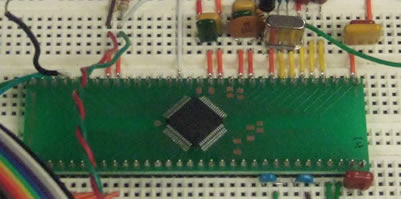
The audio signal is fed into the analog input on the MP3 encoder chip. This chip has internal ADC and DSP components to encode the incoming analog audio signal to MP3 format. It also incorporates many configurable settings such as: volume level, quality control, base boost, sample rate, etc.The chip required many external electrical components to ensure proper communication.
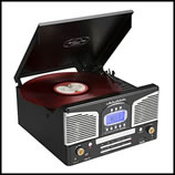
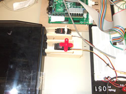
Record Player
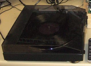
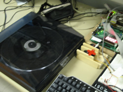
AT-PL50 Audio-Technica Record Player
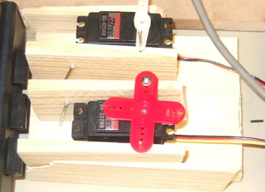
We used the record player to get our audio data -- although our design would also allow you to simply use any incoming analog audio signal and bypass the record player. We had originally hoped to control the player's motor and needle-arm electrically with relays; however, upon disassembly we observed that everything was linked mechanically and that integrating our control mechinisms would be very difficult. We thus decided to use servos to push the external start, stop, and pause buttons.
Servo Motors
Software Design
High Level Software Flow
Since assembly language programming sucks, we tried to avoid it at all costs. Thus everything is written in C except for: the ISR handlers, the device drivers which put out a character on their respective device/bus, some special register initializations, and the _start function.
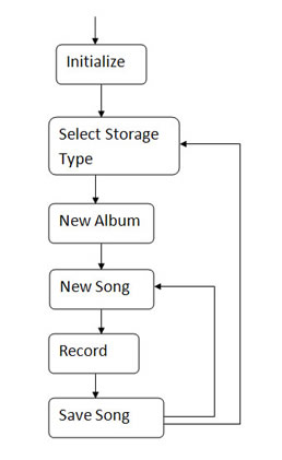
Our code is broken down into 6 major stages:
Initialize
The initialize stage of our program was used to setup the I2C and SPI host controllers on the MPC823 as well as the system interface unit. This section also initialized the MP3 encoder fields and the LCD display. We also mounted the USB keyboard and defaulted the file storage system to USB.
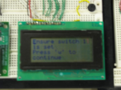
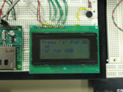
Select Storage Type
In this stage, we first displayed a prompt to the user to select a storage device. We then polled the keyboard to get the user input and mounted the selected device via SPI to the USBWiz.
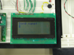
New Album
In this section, we displayed a prompt to the user to input an album name. We then use this input to create a directory of that name on the storage device and change to that directory. Input is gathered through SPI from the USBWiz's keyboard. We stop polling the keyboard after the user has pressed enter; however, due to the constraints of our FAT system, we only consider the first 8 characters of input (and either concantonate '_' to get 8 characters or chop off any input characters after 8). Creation of the directory is also accomplished through SPI to the USBWiz's previously mounted storage device.
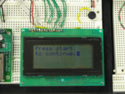
New Song
This section is pratically identical to the New Album stage, except this time, we prompt for a song, and use the input to create an empty MP3 file of that name (instead of a directory). After the file name has been input, we display a prompt to press the start button (on the FPGA), which will move the user to the Record stage. This is implemented by the button generating an interrupt which changes an internal variable containing our current software state.
Record
During this stage, we first send commands to the servo motors to push the button on the record player. We then have a small wait state because the mechanics of the record player are quite slow and it takes a few seconds from when you press start to when you actually get music out. After this, we send commands to the MP3 encoder via I2C to start the encoding. When the encoder has data, it gets sent to our custom FPGA receive buffer and raises an interrupt (see hardware description of MP3 encoder). The ISR then transfers the 30 bytes of data to an internal memory buffer in the MPC823 and updates a pointer to the end of this data. Our main loop is continually writing this internal buffer onto our created MP3 file via SPI to the USBWiz; however, we could only write data when the USBWiz was not busy and thus had to continually check the busy pin which we had mapped through the FPGA as a memory mapped I/O device. During this stage, we display the name of the current song and directory which we are saving on the LCD. We exit this stage once the user presses either the stop or pause buttons (on the FPGA). This raises an interrupt and the ISR activates the servo to press the respective button and deactivates the MP3 encoder via I2C.
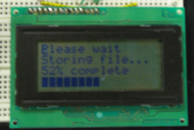
Save Song
We discovered that the USBWiz is considerably slower than the MP3 chip, and thus had to create this stage in our programming to save the internal buffer of the MPC823 once the encoder has stopped sending data. During this stage, we display a message with the current percentage of the file which has been stored. We continue to write the internal buffer to the storage device via SPI to the USBWiz until all of the buffer's data has been stored. We then loop back to the New Song stage if the user had pressed the pause button to exit the Record stage, and loop back to the Select Storage section of the user had pressed the Stop button.
Results of the Design
Our first roadblock was implementation of USB on the MPC823. We spun our wheels for a few days before concluding that the 48MHz clock required was too fast for the kit (see appendix). To solve this we ordered the USBWIZ converter chip. The chip worked reasonably well, except bulk USB transfer was extremely slow - taking almost 4mins/MB.
This speed constraint did cause us to change our program flow. Initially, we thought we would be able to stream data to the USB thumb drive, allowing real time encoding. However, due to the 4mins/MB ceiling, we had to design a circular buffer on the MPC, as well as actually pause the encoding process between songs while we transfered data.
In whole, the system integrated well and worked correctly. Given another week, we would have solved the USB speed transfer issue and made the system more robust.
Conclusions
Given our components, the Vinyl to MP3 Transcoder was able to be built. It did function as planned, allowing us to encode a given record to organized MP3's on a thumb drive. However, from a real world perspective the transfer speed was just too slow. Our bottleneck was not processing power, but the USBWIZ. It was not designed for fast bulk transfers. As such, most of the time was spent in loops waiting for the USBWIZ to become ready and accept another data packet.
With the wisdom gained over the past few weeks, we would not have spent time trying to get USB working on the MPC itself - it simply is not possible given the kit's restraints. Secondly, we would have done more research in finding a more suitable USB converter - one that could handle faster speeds.
Media
Appendix:
USB host mode on the MPC823
We had initially planned to use the MPC823's host controller to directly talk to a USB mass storage device from the MPC823. We had reached the point where we could successfully send data, token, and handshake (with their required Syncs, CRCs, and EOPs) packets over the MPC823's USB ports and were beginning to work on which packets we needed to send to the mass storage device to setup the FAT system and write our data. We then began integrating hardware and discovered that USB host functionality can not be implemented on the MPC823 if you would like to use the expansion board. The reasoning is as follows:
1. The USB host controller on the MPC823 only supports full speed mode -- 12 Mbits/s.
2. The USB host controller on the MPC823 requires a clock speed of 4 times the data rate -- thus must be 48 MHz
3. The Expansion board receives a clock speed of one half the processor speed -- thus 24 MHz.
4. The capacitance of the Expansion board is such that at 24 MHz, all signals through the expansion board are destroyed. Thus preventing you from running the USB host controller on the MPC823 as well as using the expansion board.
USBWiz Level Converter
To load firmware onto the USBWiz device, we needed to build a RS232 to TTL level converter. With this converter, we could use Hyperterminal to send commands to the USBWiz through UART. This is the only was to load the initail firmware onto the USBWiz. See our references for a level converter schematic.
Graphic Visualization
Initially, we had planned to include a graphical visualization of the music being recorded. This was implemented in software, but there was not enough spare processing time to refresh the display while recording.
References:
USBWiz Resources:
http://www.ghielectronics.com/details.php?id=5&sid=6
MP3 Encoder Chip Resources:
Chip Source
http://www.snailinstruments.com/eng/
Data Sheet
http://www.snailinstruments.com/docs/mas3587f.pdf
Similar projects:
http://www.stanford.edu/class/ee281/projects/aut2002/kuzuhara/PandM.html
http://home.intekom.com/ral/
http://www.dragonmp3.tk/
Expansion Board / Display Resources:
http://home.iae.nl/users/pouweha/lcd/lcd.shtml
http://www.eecs.umich.edu/courses/eecs373/Labs/devices/hd44780u%20controller%20spec.pdf
http://www.eecs.umich.edu/courses/eecs373/Labs/373%20Project%20IO%20Expansion%20Kitise.pdf
Freescale MPC823 Example Drivers:
http://www.freescale.com/webapp/sps/site/prod_summary.jsp?code=MPC823&fpsp=1&tab=Design_Tools_Tab
RS232 Level Converter
http://sodoityourself.com/max232-serial-level-converter/