|
|
PROJECT
RADAR By: Doug Hill Zachary Salzbank |
|

Table of Contents:
INTRODUCTION:
The original project idea was to create radar system that could be mounted on a remote control car. This system would allow the driver to see detected objects on an LCD screen and navigate the car accordingly. The radar could be set to scan the entire area or to allow the user to manually choose a scan direction if a specific direction is more immediately required. Our goal was to create the radar system which could later be mounted on a vehicle (we had originally hoped for additional group members so that vehicle mounting would be feasible in the allotted time).
HIGH LEVEL DESIGN:
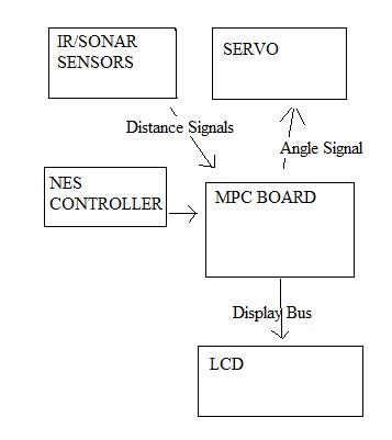
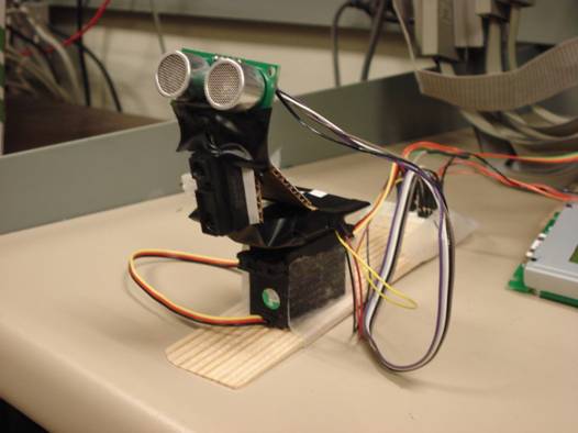
The user controls the system with an NES controller which sends control signals to the processor. A sonar and IR sensor are mounted on a servo. The processor send control signals to the servo causing it to spin to an angle based on the NES controller inputs. The sonar and IR sensor send the processor distance signals corresponding to the object detected. The processor then outputs the objects location on the LCD for the user to see.
Component: Description:
NES CONTROLLER Allows user input for navigating menus and choosing scan direction
Sonar/IR Detects objects and sends a signal corresponding to their distance to processor
Servo Sets angle of detection direction
LCD Displays menu and radar screen to user
TASK DISTRIBUTION:
|
|
Doug |
Zach |
|
Sonar |
90% |
10% |
|
IR |
40% |
60% |
|
LCD |
10% |
90% |
|
Servo |
50% |
50% |
|
Radar
Software |
40% |
60% |
|
NES
Controller |
5% |
95% |
|
Web
Site |
95% |
5% |
HARDWARE DESIGN:
Sonar:
An address decoder responds when a write command is issued to the sonar. This generates a pulse of ~10us (using a hardware created timer). An internal ready signal is pulled down until the end of the echo pulse is detected. The pulse is sent to the sonar device. When the echo signal is returned, a counter (with echo as its clock enable and a scaled BUS_CLK) begins to count (starting from 0). A 32 bit register stores this 16 bit value along with the status of the ready signal. When the echo signal returns low the counter stops counting and the ready signal is returned high. After this the 32 bit register will contain the ready signal (high) in bit 32 and the final 16 bit counter value.
Another address decoder responds when a read command is issued to the sonar and sends the value in the 32 bit resgister to data_to_proc.
IR:
An address decoder detects when a command is issued to the IR. A value is then sent from the IR sensor to the ADC. The ADC converts the voltage and sends it to data_to_proc.
LCD:
The LCD must be on a bidirectional bus. Because we use an LCD and the ADC and both must use EXP pins 0-7 the hardware had to be created to allow the signals to not conflict. This was done by setting the dir pin to the correct setting and making sure that the LCD was “shut off” or not doing anything when the ADC was being used. The LCD address decoders will detect when the LCD is being written to or when the status is being checked. A bus if data is then written/read to/from the LCD.
Servo:
The servo’s position is based on the duty cycle of the pulse being sent to it. This was done using the processor timer. When the pulse is set to high (start of duty cycle) the processor timer counts until the duty cycle value is reached (when it will throw an interrupt). The pulse is then set to low and the processor timer counts to (pulse width – duty cycle). Then another interrupt is thrown to toggle it back again.
NES:
The NES controller is polled to send its status via serial signal. When the address decoder detects the correct address it creates a latch signal. This signal is sent to the controller to tell it to latch its data. Afterwards the hardware creates a series of data pulses corresponding to the status of each button. When the controller sees each data pulse it sends the next button value over the serial bus. The latch and data pulse signals are generated using hardware counters and flip-flips.
SOFTWARE DESIGN:
Sonar:
The sonar software writes to the sonar address. The software then reads a word from the sonar address. It checks bit 32 (ready bit). If it is not ready it loops back and reads again until the ready bit is set. The ready bit is then stripped from the read value and returned as the distance measured by sonar.
IR:
The IR software polls the IR address several times for a distance. The mode of all of these results is returned as the correct distance of the object detected by the IR device.
LCD:
The majority of the LCD software writes commands and data to the LCD address. Several functions were created to map a specific command/image to its corresponding bit value.
Servo:
The servo software uses the processor timer. There is a function to convert the desired servo angle to the correct TRR value. The software then sets this TRR value. When the processor timer counts to the toggle point an interrupt is thrown to change the level of the signal being sent to the servo and the new toggle point (TRR) to period - duty cycle. It is done this way to insure a fairly consistent period and pulse width. The processor timer will always count and the interrupt will ensure that a interim processes don’t skew the period.
NES:
The NES software polls the NES address when the main function requires its values.
Most of our software is written in C. Assembly was used for code requiring interrupts (such as the servo) but everything else was designed using C whenever possible. The only other latency issues we had were to make sure that the servo had finished moving before the sensors were polled.
RADAR_Software:
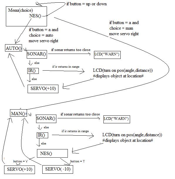
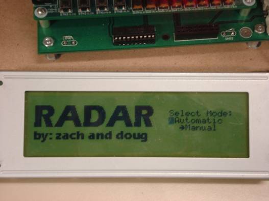
This is the main software for our implementation. It starts by initializing the LCD. Then it displays a menu and polls the NES controller. Pushing up or down changes the menu selection. This loop continues until the A button is detected. When this is detected the automatic or manual mode function is called (depending upon which selection was made).
Auto Mode:
· Servo function is called to move the servo all the way to the left.
·
(
· If the distance is under a specific value the LCD functions are called to cause the LCD to output the warning
· Else the IR sensor functions are called and if there is an object in range the LCD functions are called to display the correct place
o Note: Each valid combination of servo angle and IR distance(a range) corresponds to a specific cell on the radar screen.
· The servo function is called to increment the angle by 10 degrees
· The loop is repeated until the servo reaches all the way right.
Manual Mode:
· Servo function is called to move the servo all the way to the left.
·
(
· If the distance is under a specific value the LCD functions are called to cause the LCD to output the warning
· Else the IR sensor functions are called and if there is an object in range the LCD functions are called to display the correct place
o Note: Each valid combination of servo angle and IR distance(a range) corresponds to a specific cell on the radar screen.
· The NES() function is called until either button ‘L’ or ‘R’ is found
· If ‘L’ Servo function called to decrement angle by 10 degrees, if ‘R’ Servo function called to increment angle by 10 degrees
· The loop is repeated.
RESULTS OF THE DESIGN:
The design worked mostly as it was supposed to. The sonar sensor’s beam was very wide which did not make it usable for detecting the location of an object. It was impossible to determine which direction the object was located. Because of this we used the sonar only to determine when an object was closer than 6 inches. This ended up working very well because the closest the IR sensor was functional in our design was about six inches. Because of this the IR sensor is used only for objects far away and a warning is displayed when things are too close.
CONCLUSION:
Our original goals were mostly met up to trying to mount the device on a vehicle. With only the time we were given and the presence of only two team members, trying to go further into this development was not feasible. Our main goal was to get the radar system working correctly which was accomplished. The processing power was adequate. The biggest limitation was the speed of the device. If the device were to actually be mounted to a vehicle our system would probably be impractical because of the speed. In auto mode the driver would have to wait for the entire scan to get a good view of the surroundings. Because of the considerable amount of time this takes the driver would have to move slowly and often pause for an update. If manual mode were used it may improve things by only scanning desired locations, however the driver would still need to often wait for an update whenever the direction was changed or you moved a significant distance. Currently the biggest factor of this limitation is the servo speed. If the move-then-measure time (due mostly to waiting for the servo to finish moving) were significantly decreased the system would be more practical.
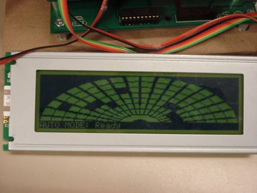
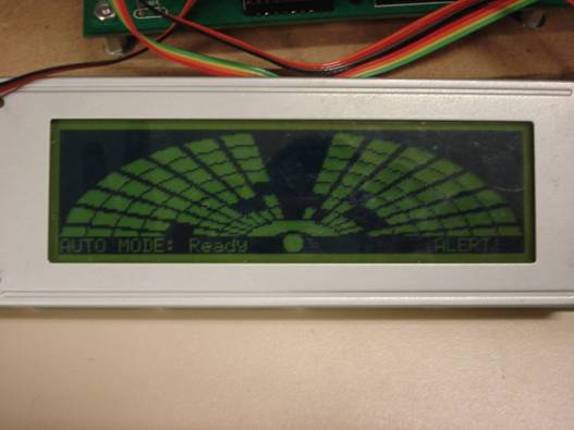
MEDIA:
|
Menu Screen |
|
Sensor Assembly |
|
Radar with IR detected objects |
|
Radar with Sonar detected “Warn” display |
REFERENCES:
LCD:
http://www.eecs.umich.edu/courses/eecs373/Labs/devices/5005cne.pdf
http://www.eecs.umich.edu/courses/eecs373/Labs/devices/T6963C%20toshiba%20data%20sheet.pdf
Servo:
http://www.robotstorehk.com/sensors/doc/srf05tech.pdf
IR:
http://www.eecs.umich.edu/courses/eecs373/Labs/devices/SharpGP2D12