Whistler Sound System
EECS 373 Project - April 2008
Team Members
- John Dydo (jdydo@umich.edu)
- Benjamin Kempke (bpkempke@umich.edu)
Introduction
The Whistler Sound System was envisioned as a hardware-based MP3 file player supplemented with additional features that would be found in a sound processing system: a microphone input mixed into the MP3 audio, a Fast Fourier Transform frequency spectrum display, and integration with the FAT16 file system using secure digital memory cards. While the fundamental goal of the project was to play MP3 files by retrieving them from a FAT16 partition and running a decoder IC in real-time, we were able to implement the additional features mentioned above, as well as a text-mode GUI and command line interface. Finally, a karaoke game, similar to the recent videogame Karaoke Revolution, was created by combining all of the audio and video functionality into one application.
High Level Design
As a compressed audio-based project, the main component required was an MP3 decoder of some kind. From the onset, it was clear that a software decoder would not be feasible, so a commercial Integrated Circuit decoder would have to be interfaced to our hardware. Because of the high bandwidth of audio, interfacing any CD-quality audio-related components was expected to be challenging for the prototyping tools we used in the project.
A design rule we followed was that if a data stream was moving too slowly through the microprocessor system, then dedicated hardware would be created in order to enable parallel processing of data moving between all of the audio-related devices. This action was taken in most instances as most of the data processing was offloaded to the FPGA hardware in the final design.
Research was done to see what options we had for frequency analysis, and we found that a working FFT IP core was readily available as a Xilinx hardware component. This component gave an easy way to break the sound data into frequency ranges and further into musical notes in real-time hardware.
Another feature was to utilize the analog joystick of the Nintendo 64 controller to pan and fade sound between four speakers. This required an algorithm to attenuate the signal to each speaker depending on the digital reading received from the controller.
We also knew that some kind of rich display was needed to show the file names on the memory card as well as to support the gaming functionality. Originally the graphics LCD was going to be used for this, but the availability of a VGA text-mode interface upgraded the graphics capabilities of the project.
Member Task Distribution
In order to reduce development overhead, the hardware and software portions were strictly split between team members. This plan worked well for integration since all that was required to test a new version of the system was either loading a new FPGA configuration file or a new software file, instead of having to combine source files from multiple sources and compile in-sync for every revision.
Ben's Tasks
- SD Controller
- LCD Controller
- FFT on FPGA
- A-D Converter (Microphone)
- D-A Converter (Dual 44khz stereo sound)
- VGA Controller
- N64 Controller
- 3D Sound Panning
- PS2 Keyboard Controller (Modified from opencores.org)
John's Tasks
- Interfacing hardware devices
- FAT Partition reader
- I2C Controller
- Interfacing MP3 Decoder IC
- DOS terminal emulator
- Windowed GUI
- ID3 Tag reader
- Karaoke Game
Hardware Design
SD Controller
A basic SPI-based SD Card reader had already been developed (prior to this project) in Verilog for accessing data stored on the SD card in sequential order. While this was adequate for the introductory curriculum of another class, reading a FAT partition requires non-sequential access. To satisfy this constraint, the controller was modified to accept random access of data on the memory card for when the software-based FAT reader needed to seek to a different address.
LCD Controller
The Graphics controller was originally meant to be the main focus of our project, displaying song information and game-related graphics. The LCD display was ultimately relieved of this task as the superior VGA display format was used in its place. We found that a FFT visualization was a better use for the limited display, showing the frequency spectrum from 1-2000Hz across its length on a logarithmic scale. A block memory unit on the FPGA served as a duplicate of the memory contained on the display, with each being continuously synchronized with one another, creating a much faster way of updating the display on-the-fly than individual writes would serve.
FFT on FPGA
Xilinx provided a suitable IP Core that processed the incoming data from the microphone's A-D converter in real time. A 1024-point FFT core was chosen because it provided a frequency resolution that fit our project well. The controller, that was developed as a wrapper around this core, automatically processed the data and updated the graphics display accordingly. An index into the FFT output was also maintained to keep track of the dominant frequency being picked up by the microphone. This value was then converted into its corresponding chromatic scale note equivalent, and sent to the PowerPC for more analysis within the karaoke add-on.
Analog-to-Digital Converter (For microphone)
A condenser microphone was integrated into the system for use as the input to the frequency analyzer, as required for the karaoke game add-on. After the analog signal produced from the microphone was amplified and conditioned, it was then passed on to the A-D converter. In order to provide the high-fidelity sound needed, the on-board ADC was not fast enough to capture the frequencies produced from whistling. An ADC capable of providing up to a 200kHz conversion rate was used, sampling at a CD-quality rate of 44kHz. The resulting digital data was clocked into the expansion board to the FPGA.
Digital-to-Analog Converters (For dual 44khz stereo sound output)
The MP3 chip outputs its data at the clock rate given by the MP3 file that it is playing. In most cases, this is a rate of 44 kHz and appropriate DACs were needed to accommodate this rate. Two DACs with I2S interfacing were chosen and could be interfaced directly to the STA013 MP3 decoder chip. However, the decompressed MP3 data was instead processed by the FPGA and sent back out to the two stereo DACs a full cycle later. This gave us the ability to include panning and fading effects through 4 surround speakers, implemented using the joystick position passed back from the N64 controller.
VGA Controller
An expansion port on the Xilinx board provided VGA output capabilities to an external monitor. A palette of eight basic colors was possible, and a 640x480 VGA Controller was implemented in Verilog. Given the Block-RAM limits on the FPGA, and limited access to the greater SRAM chip, a simple DOS-formatted character display was made to conserve space. With an 80x40 character display with eight foreground and background colors, this provided the necessary means to create the GUI frontend of our system.
N64 Controller
The game controller originally implemented for the Nintendo 64 game console proved to be easily implemented in Verilog. Care was necessary to implement the bi-directional data bus, and a 1MHz clock rate was necessary to maintain accurate polling and sampling from the controller. Each data packet received contained data for 16 buttons and the joystick position. Certain buttons provided feedback control for software functions such as Pause/Play/Stop, and the joystick's value was utilized in the panning and fading across the four surround speakers.
2D Sound Panning
One of the final features added was the functionality to control the perceived location of the sound through manipulating the volume in each of four surround speakers. By using the joystick data received from the N64 controller, the volume of each respective speaker was manipulated depending on the direction in which the joystick was pointing. By lagging each sample received from the MP3 decoder chip by one cycle, this data was then passed through each speaker's respective hardware-based multiplier that was already supplied on-chip to scale the amplitude accordingly. By then passing this processed data to the speakers through the two stereo DAC chips (PCM1725), a convincing pan-fade effect similar to that implemented in many current stereo systems was realized.
PS2 Keyboard Controller
The Keyboard interface was a Verilog implementation modified from opencores.org. Please visit the webpage given in the references section for more details about the PS2 controller.
10 Hz Timer
An accurate 10Hz timer was implemented and sent to an interrupt request pin for
use in the software's song timing and game modes to provide real-time graphics
updates.
Software Design
In order to prevent complications during project development, all software was developed by one team member. An improved batch file was developed to find compilation errors from all of the source files being processed with more clarity. A macro system was developed to access the MPC823 memory-mapped registers easily from C code, relegating assembly usage to only the bootstrap code. Near the end of development, the maximum number of source files input to the linker was reached, leading to much of the final functionality being coded into one large source file.
FAT Partition reader
One of the goals of the project was to interface with standard memory card formats that are used in modern computers. Both a hardware and a software component were required to complete this goal. As described above, a Secure Digital card reader was implemented in hardware. On the software side, it was decided that a FAT file system reader was required as this is the standard partition format for most memory cards.
Documentation on the FAT16 file system was surprisingly sparse, but its simplicity has allowed for reverse-engineering by many individuals. A small number of web pages (given in the references section) were used to calculate the offsets of relevant data (such as the location of the File Allocation Tables and cluster offset calculations). Directory listing and file stream functions were then implemented in just a few hundred lines of code. In order to have adequate bandwidth for MP3 streaming, the block size transferred at every read had to be increased from one word to one 512-byte sector per read function call.
I2C Controller
The first barrier to integrating the STA013 MP3 Decoder IC was initial configuration data that needed to be sent over the I2C bus. Before the chip would function, it needs to have a 4 kilobyte configuration file streamed over I2C. In addition, its PLL registers must be programmed based on frequency of the external clock signal it is receiving. Fortunately, a complete I2C bus controller is provided in the Communication Processor Module of the MPC823.
Although the onboard controller is a versatile and high-availability transceiver, only rudimentary usage was required for STA013 configuration. Single byte read and write functions were developed using the I2C usage example given in the MPC823 manual. Once these functions were implemented, the required configuration data was imported as C source to be sent on system start up. These vectors are streamed byte-by-byte, with all configuration taking place in under a second, once the I2C data clock was increased.
Interfacing the MP3 Decoder chip
After configuration over I2C as described above, MP3 file data is to be streamed over a simple serial line as long as the chip has its request line asserted. That is, the chip has a request signal when it needs data, and it must be given data or else it is at risk of under running the input data. The MP3 play loop was based on polling this pin instead of interrupting when this pin was asserted since it would be likely that interrupts would be generated too often, and the ISR would occasionally need to take an extended amount of time when reading in a new sector or data.
Windowed GUI
After the VGA hardware was developed, it was clear that a structured display system would be useful for song selection, information display, and game animations. Since bitmap graphics were not feasible because of memory requirements, text mode graphics had to be used. A subset of the ASCII character set was implemented in the character generator hardware. Besides normal characters, line drawing characters were included to draw simple shapes on screen.
A windowing system was developed in C using data structures containing just a few pieces of information such as location, size, and background color of each window. All of the onscreen data is kept in memory in order to be able to repaint as well as scroll text content upwards.
DOS terminal emulator
Since this project included file selection and text display, it was natural to add a command line interface to the GUI. The availability of the keyboard made this reasonable to implement. In order to implement the command line interface, many standard C functions for keyboard input and string manipulation were implemented from scratch in order to allow adequate input and output functionality.
By using the output data structures of the FAT16 partition reader (including directory traversal, file names and sizes), the DOS commands "dir" and "cd" were implemented. Additional commands implemented included "mp3player filename" to start the media player as well as "game filename" to start the karaoke game with a premade game file. When the command parser recognizes any of these commands, the appropriate handler function will be called.
ID3 Tag reader
ID3 tags are text data structures embedded at the beginning of MP3 files which provide a wealth of information about the song that goes beyond what could be fit into the filename. Because the MP3 decoder has no knowledge of ID3 tags, it was necessary to implement the ID3 tag reader in the software that streams the file data to the MP3 decoder.
The tag reader works by snooping the file data as it is sent to the MP3 chip. When 4-byte tags are encountered that are indicative of an ID3 field, the associated string is copied into the designated string buffer. This string is then drawn in the appropriate spot of the media player window.
Karaoke Game
The culmination of the project was the development of a karaoke game similar to the recent video game "Karaoke Revolution". Voice pitch measurement is used to give the player a score of how well they are singing the song. An on-screen scrolling display shows what musical notes are to be sung, in a scrolling display similar to that seen in the game "Tetris". Whenever the player correctly sings the note at the top of the scrolling display, their score will be incremented and updated at the bottom of the screen.
In order to implement the game animation, the previously developed command line drawing and scrolling functionality was reused. Gameplay needed to run at a timed interval, and we decided that five updates per second would be adequate resolution for song timing in the game. After experimentation, timing using the MPC823 Communication Processor Module timers did not seem to run at the correct interval. The solution was to use a simple timer on the FPGA (described in the preceding section) linked to an external interrupt request. The interrupt handler calls the game loop C function to scroll the window, add a new note, and update the player's score based on the reading from the FFT musical note input port.
Results of the Design
Over the course of working on this project, many difficulties arose during its
design. The speed of the processor was found to be sub-optimal for delivering
data to the MP3 chip at a fast enough rate and providing any of the audio
manipulation capabilities desired. These problems were resolved by making
dedicated hardware in the FPGA to feed data to the MP3 chip and process the
resulting data from the STA013.
The microphone converter chip chosen for this design was not the initially of
the correct type. The converters originally obtained were in a Delta-Sigma
format, which is not useful for our audio application as they only output the delta change between each
sample value. Luckily, all the converters used in the project were compatible with the I2S format, so
replacing converters came down to being only an electrical task (i.e. replacing capacitors).
When first using the FAT partition reader, only a few bytes were read for every call into the FAT driver, which causes far too much overhead for reading through a whole MP3 file. The solution to this problem was to turn it into a block mode driver than transferred a whole sector of 512 bytes for every call to the driver. Each byte was then sent to dedicated hardware that shifted the data out to the MP3 decoder, instead of making a software shifter that would toggle output wires.
Audio stutter problems were also initially caused by the display driver. When scrolling the game display, so much processing would occur that the MP3 input buffer would underrun and audio would momentarily pause. The solution was to optimize the scrolling code and also to shorten the height of the display (which did not compromise the game functionality). An alternate solution would have been to connect the MP3 data request line to an interrupt, so that the GUI code could be interrupted, instead of the other way around. This was not done because the data request line seemed to interrupt too often causing a great amount of overhead and slow down.
Another problem was related to finding partition information on the memory
card. Due to details of USB implementation on Windows, when a memory card is
formatted it may or may not have the
Master Boot Record (MBR) easy to locate. When a second memory card was used during development, the
MBR was nowhere to be found. The solution was to assume that the first sector
was the FAT16 boot record, and reading the partition could immediately begin
with this sector.
One unresolved problem was that during playback the MP3 decoder would sometimes
not respond to I2C queries for playback information at seemingly random times. This may be due to the
current state of playback or the result of an error in the MP3 file. This
problem was evident when querying for the number of sound frames played, which is
required to calculate the time elapsed into the song. The solution was to
instead use our 10Hz hardware timer to calculate time elapsed.
Conclusion
Ultimately, we proved that it is possible to implement the MP3 karaoke machine that we had set out to develop. All of the hardware utilized in this project was more than adequate for the task it was intended for, especially due to the power of the FPGA hardware. If more time was given, the hardware could have been refined to better pick up human voice, by selecting a better microphone and providing better audio filtering of microphone input to mute any noise such as that produced from the singer's breath.
Media
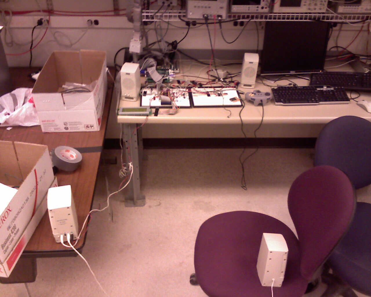 |
Overall view of project, including placement of four speakers. |
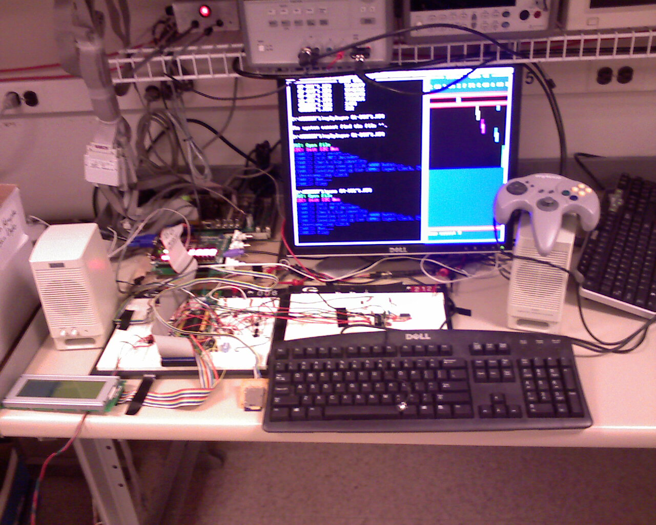 |
Overall view of project, showing hardware and software. |
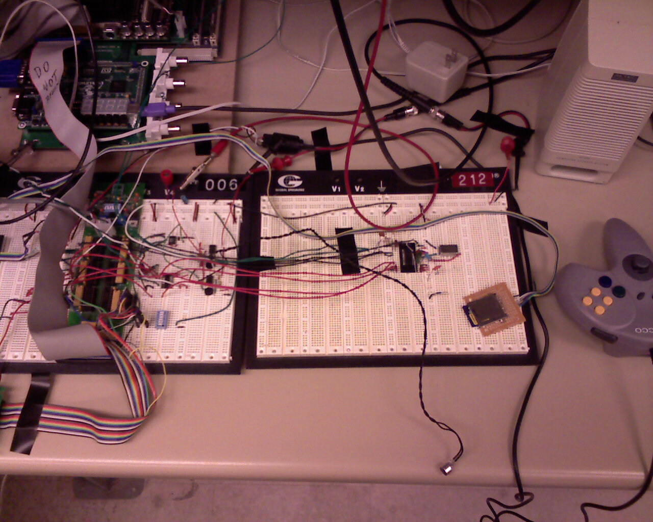 |
Overview of the hardware spread between two breadboards. |
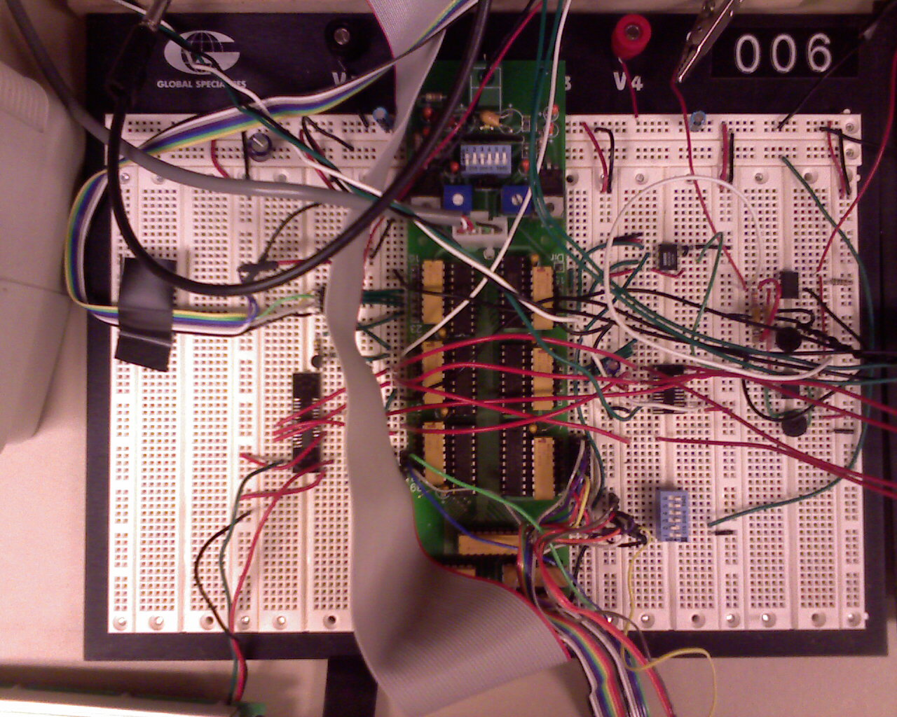 |
Close up of connections to expansion board including two D-A converters (left and top right) and A-D with microphone. |
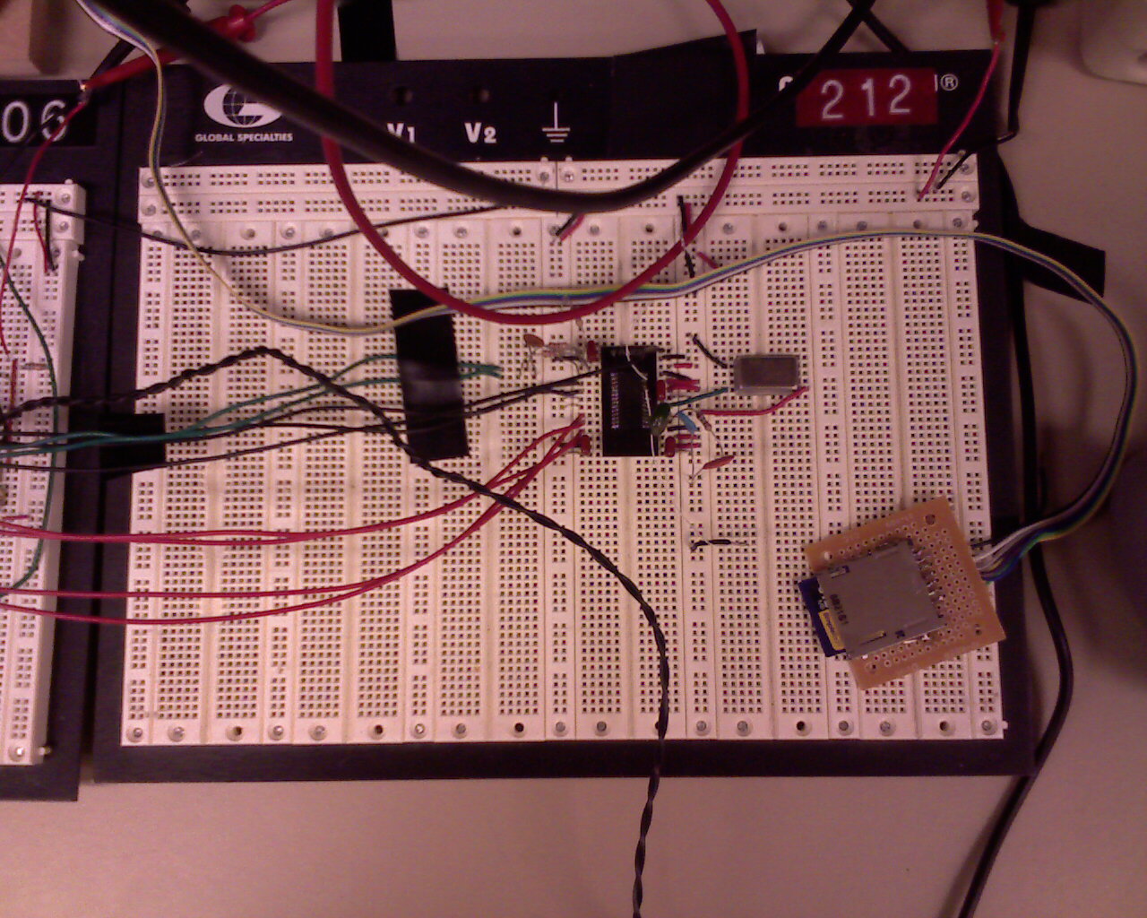 |
Close up of MP3 decoder IC and SD card socket. |
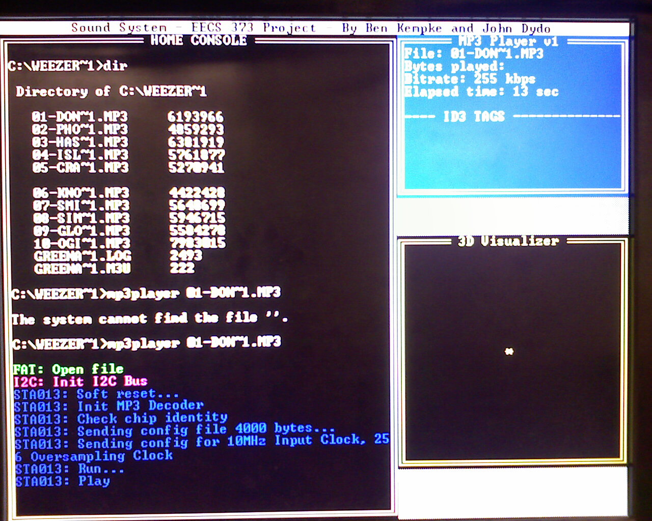 |
Software operation under the media player. |
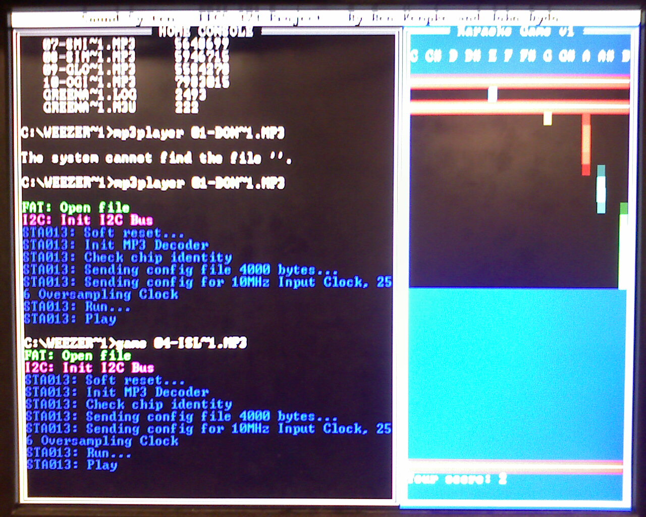 |
Software operation during the karaoke game. |
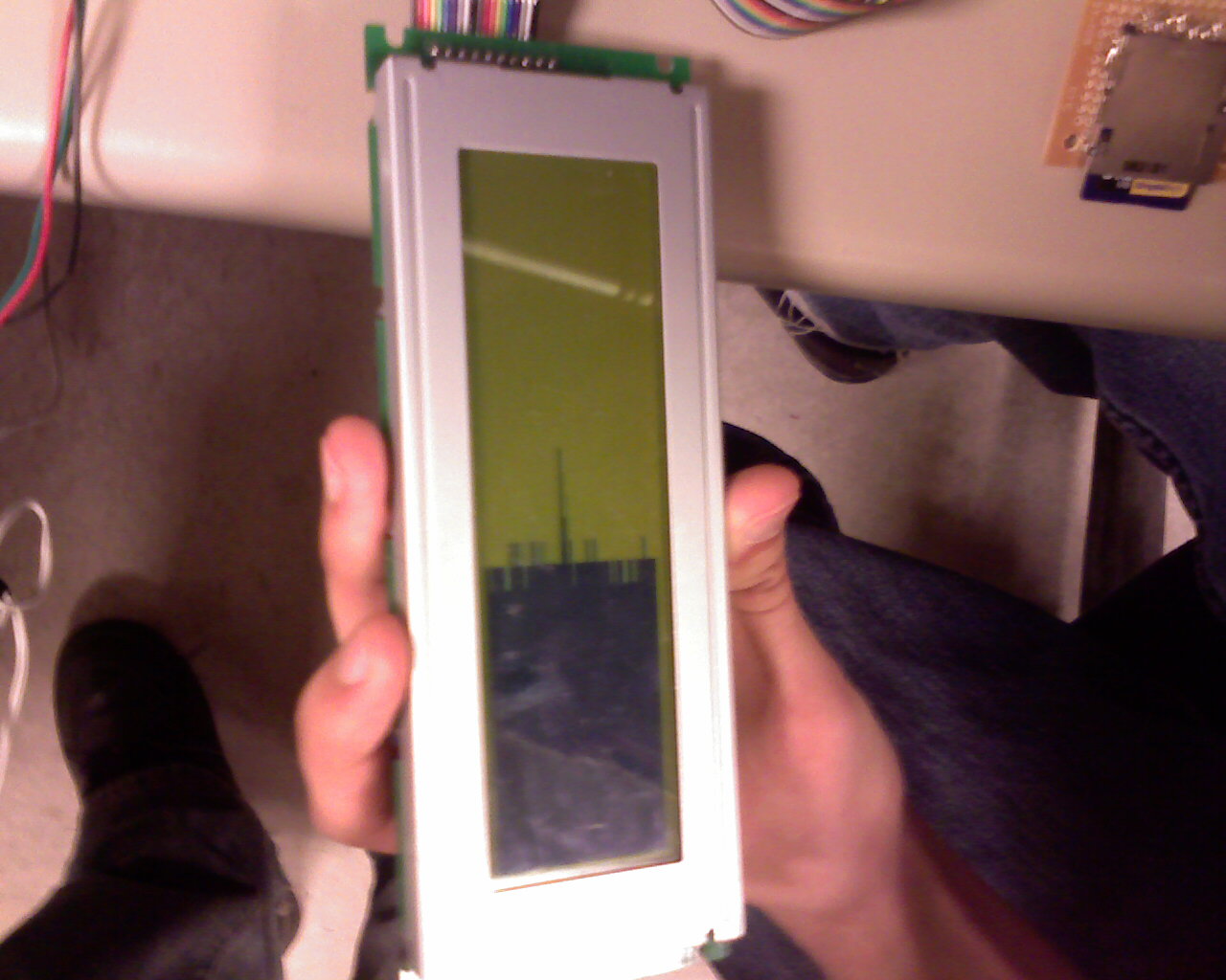 |
FFT spectrum analyzer, shown with a certain note being whistled into the microphone. |
References
- FAT16 Structure Information - Written by Jack Dobiash File Allocation Table - 16bit
- STA013 - The original ST MP3doc™ "decoder-on-chip" solutions for portable music players
- MP3 Player, How To Use The STA013 MP3 Decoder Chip
- PCM1725 - SoundPlus(TM) Stereo Audio Digital-To-Analog Converter 16 Bits, 96kHz Sampling
- 12-Bit High Speed 2.7V Micro Power Sampling Analog-To-Digital Converter
- Opencores.org - PS2 Interface