EECS 487, Fall 2005
Project 3: Sketch
Overview
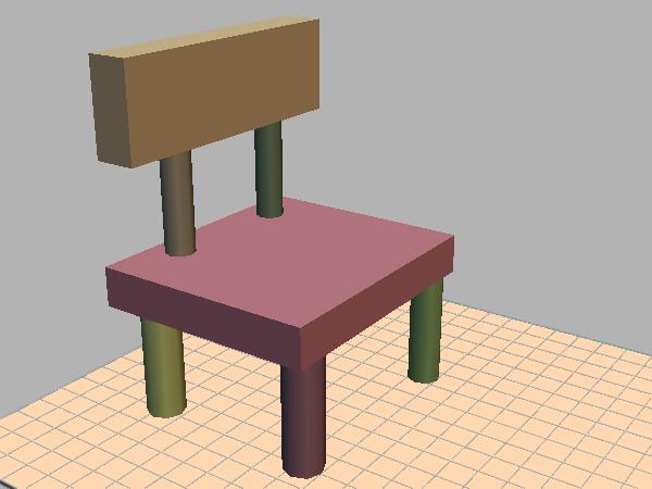
In this project you will implement a simple sketch-based modeling system. The basic system supports two kinds of primitives (or basic shapes): boxes and cylinders. Extended versions of the system support additional primitive types such as spheres, ducts, surfaces of revolution, and extruded shapes. Each primitive type is matched to a set of input gestures, which are 2D strokes drawn by the user. The user can thus create a 3D scene interactively by "sketching" various primitives.
In addition to sketching shapes with the left mouse button, the user can move existing shapes around using the middle button. Every shape is given a constraint that limits how the shape moves when grabbed by the user via the middle mouse button. Initially, each object is constrained to move in the plane of the surface on which it was created. The user can interactively define new constraints to move the object in a different plane, or along a given direction. Primitives are organized into a hierarchy via nested transforms. When a new primitive is sketched on top of an existing one, it is added to the scene as a "child" of the existing one, meaning it is defined in the coordinate system of the existing primitive. When the existing one is moved, all of its children automatically move with it. But when a child is moved, it moves independently.
This project is loosely based on the SIGGRAPH 1996 paper: SKETCH: An Interface for Sketching 3D Scenes. (We will see the video in class.)
You are given support code for this project and will need to:
- link to the jot
library, and
- copy the project support code and edit the makefile to indicate jot installation information, and
- implement the missing functionality.
Support Code
Copy the project support code to your local machine using one of the following commands:
Remote session for Linux/Unix/SunOS/MacOS users:
  % scp -r red.engin.umich.edu:/afs/engin.umich.edu/class/perm/eecs487/proj3 .

                OR

  % rsync -av -e ssh red.engin.umich.edu:/afs/engin.umich.edu/class/perm/eecs487/proj3 .
Windows users can use set up an sftp session to red.engin.umich.edu and grab the files from the above path or, on (CAEN) machines with AFS mount, copy the files from:
K:\perm\eecs487\proj3
The C++ source code files are: axis.C axis.H floor.C floor.H node.C node.H node_manip.C node_manip.H p3.C sketch_pen.C sketch_pen.H. These provide useful functionality, but not everything is implemented. Read through these files to get familiar with them, then implement the following missing functionality (usually marked by the phrase "YOUR CODE HERE"). You are permitted to modify any of the provided source files as you see fit.
Basic primitives:
- Complete the unfinished parts of sketch_pen.C that handle the
creation of boxes and cylinders. The
provided support code already
checks the user's input strokes and classifies them according to
various types, such as straight line, tap, and curved stroke. In the
function SketchPen::line_cb(),
each
straight line drawn by the user is compared to three "canonical" 3D
axes (described below). When a canonical axis (projected to image space
at the start of the user's stroke) and user-drawn 2D line are
sufficiently
parallel (in screen space), the support code creates a 3D line segment
(using class AXIS,
defined in axis.H)
that is parallel to the canonical axis and whose length corresponds
to the user's stroke. The AXIS
class keeps a list of all currently active axes in the scene. This list
should be cleared every time a new primitive is finished, or when the
user makes a "tap" gesture (see SketchPen::tap_cb()).
In the function SketchPen::line_cb(), if no axes currently exist, the system should record the (world space) 3D point p and surface normal n corresponding to the start of the user's stroke, as well as the scene object G that contains p. (G is of type NODE, a subclass of GEL, which stands for "geometric element" and represents a generic object in jot that can be added to the sccene.)
- When the user draws 3 mutually perpendicular axes, the
function SketchPen::create_box()
is called to create a box and add it to the scene.
The provided code shows how to create a new NODE N to represent the box, and add it
to the scene as a child of G
(meaning G's transform also
affects N). However, the code
does not assign the correct transform T
to N. The desired end result
is to map
the canonical cube (created in the support code) to world space so that
it matches the orientation and dimensions of the axes. E.g., you could
define the desired box to be the minimum box that is aligned to the 3
axes and contains
them. Alternately, you can make the simplifying assumption that the
three axes either start or end close to p. This makes some input illegal
that might otherwise be handled, but is probably easier to code. You
can proceed either way. In any case, T should be chosen so
that, when combined with the transform from G's object space to world
space, the canonical cube is scaled, rotated, and translated to
match the desired shape. The helper function SketchPen::obj_to_world()
returns the matrix that maps from G's
object space to world space, and SketchPen::world_to_obj()
returns the inverse matrix. 15 points
- If the user draws 2 parallel axes instead of 3 perpendicular
ones, the function SketchPen::create_cylinder()
is called to create a cylinder. Complete the implementation of this
function to create a cylinder that is parallel to the two axes (in
world space), whose base is adjacent to p, whose height is the length of the
first axis, and whose diameter is chosen so that the cylinder lies
approximately between the two axes (in image space). 15 points
Whether the user creates a box or cylinder, you should call the method NODE::set_plane_constraint() to restrict N to move in the plane perpendicular to n. (This default plane constraint can be changed by user, as described below.)
- The provided support code in SketchPen::line_cb() is not very smart about how it chooses the "canonical" axes x, y, and z: it just takes x = (1,0,0), y = (0,1,0), and z = (0,0,1). You should change the code in SketchPen::line_cb() so that y = n (the surface normal mentioned above), and x , y, and z form a right-handed orthonormal basis. Preferably, x and z should line up with the features of the parent node G. E.g., if G represents a cylinder, then at a point on the side of the cylinder, x and z would span the tangent plane, with x pointing along the length of the cylinder and z pointing across it. If G is a box, the directions should line up with the axes of the box. 10 points
- The NodeManip class
defined in node_manip.H
is intended to let
the user move objects around by grabbing them with the middle mouse
button. Mouse down, motion and up events trigger callbacks to NodeManip::down(), NodeManip:move(), and NodeManip::up(), respectively.
Finish the implementation of these functions to move objects according
to the user's input stroke. 15 points.
In NodeManip::down(), determine the node N (if any) grabbed by the user, and check whether N is constrained to move parallel to a given 3D plane (if NODE::constrain_plane() is true) or line (if NODE::constrain_line() is true). Then find the 3D point x on N's constraint plane or line that is closest to the current mouse location. To do this, construct a 3D line from the mouse location (use class Wline), and find its intersection with the constraint plane or line (using Wplane::intersect(Wline) or Wline::intersect(Wline)).
In NodeManip::move(), find the new point x' on the constraint line or plane corresponding to the new mouse location. The desired translation is then x' - x. This translation should be expressed in the coordinate system of N's parent. Apply the translation by calling the method NODE::mult_by() (inherited from the base class GEOM). After applying the translation, replace the "old" location x with the new one: x = x' (to be used the next time NodeManip::move() is called).
- Add the ability to define new constraints for nodes. If the user grabs a node when a single axis is active in the scene, in NodeManip::down() you should define a new constraint (via Node::set_line_constraint()) for the node that restricts it to move parallel to the axis direction. If there are 2 active axes, and they are not parallel, you should define a plane constraint for the node (via Node::set_plane_constraint()) restricting it to move parallel to the plane whose normal is the cross product of the two axes. After creating a new node, always clear the set of active axes using AXIS::clear_axes(). 15 points.
- Implement a custom renderer for your sketch system. Something
based on toon shading and/or sketchy lines rendered along silhouettes
and creases (or both) could be appropriate, but you are free to
implement any rendering style you choose. It is okay to use GLSL. If
you do, please mention it in your write-up so we can be sure to run
your system on a suitable platform. 10
points.
- Use your system to create an interesting scene, including
geometry, lighting design, and rendering style. Render the scene from
an interesting viewpoint, grab a screen shot and and show the class by
posting the image on the phorum as an attachment. Please use
the thread dedicated to project 3 images. You can post multiple
images. 5
points.
- Described below. 5 points.
- Comment your code reasonably, particularly your design decisions
and choice of approach.
- Modularize your code: use a suitable number helper functions with descriptive names.
- Use descriptive variable and function names: apply a suitable tradeoff between symbol-length and descriptiveness.
Extended system (up to 15 bonus points):
The following are optional, but can be attempted by ambitious students:
- Implement additional primitives, mapping them to gestures of your
choice. Possible ideas are: sphere, duct (i.e., a tube that
follows the path of a curve in 3D), surface of revolution, and extruded
shape defined from a planar shape. Corresponding gestures might be as
follows. Sphere: draw a circle and tap the center. Duct: draw a circle,
then draw a free-hand stroke from the center of the circle. Surface of
revolution: draw an axis, then draw a "profile" curve indicating the
shape to sweep around the axis. Extrude: first draw a planar shape by
drawing its outline, then draw an axis perpendicular to it to define an
inflated shape composed of 2 copies of the outline shape offset from
each other, and joined with a ruled surface.
- Add support for an additional type of motion constraint: rotation. If the user grabs a node with the middle button while a single axis is active in the scene, then the constraint should depend on the user's initial motion (the first few mouse motions while the cursor is still near the down point). If the motion is roughly parallel to the axis, use a line constraint as before. But if the motion is cross-wise to the axis, activate a rotation constraint that restricts the node to rotate around the rooted vector defined by the axis.
Building and running the code:
Edit the provided Makefile to define the path to your jot directory. [On Windows, you must use a DOS prompt, and you must first run the setup.bat script in your jot directory.] Then you should be able to compile the program, as follows:
% cd proj3This results in an executable named p3 which takes model files as command-line arguments. Before running the executable, be sure to define the JOT_ROOT environment variable to specify the path to your root jot directory. E.g.:
% make
csh or tcsh> setenv JOT_ROOT /afs/engin.umich.edu/class/f05/eecs487/jot
bash> export JOT_ROOT=/afs/engin.umich.edu/class/f05/eecs487/jot
DOS> set JOT_ROOT=K:\f05\eecs487\jot
See the phorum post on setting these variables automatically each time you start a shell to avoid having to type these in each time. For windows users, this variable is set as part of the setup.bat file that is in the jot directory.
Handing in
Copy all your project source files (no models, no binaries), and also copies of any images you posted to the phorum, to
/afs/engin.umich.edu/class/f05/eecs487/submit/<your-uniqname>/p3/ [Linux users]
K:\f05\eecs487\submit\<your-uniqname>\p3 [Windows users]
Note: put your files directly into the p3 directory specified above -- do not put them inside a separate sub-directory.
For submission from a remote, non-CAEN machine you can scp or sftp your files to the respective paths on red.engin.umich.edu
Your files should include all of the project 3 source files, whether you modified them or not, and a brief write-up, named writeup.pdf, in PDF format that discusses:
- anything about your implementation that is noteworthy, including high-level descriptions of the strategies you used to implement the required functionality, or any extra credit functionality, and
- feedback on this assignment, including suggestions for how it should be changed next time.
/afs/engin.umich.edu/class/f05/eecs487/jot
OR
K:\f05\eecs487\jot
Modify your Makefile accordingly before submission!
Test the compilation when you submit!
Multiple submissions:
- You are allowed to overwrite your files in the above directory as
many times as you want.
- If the timestamp on these files is past the deadline your submission will be considered late.
- Test this submission procedure and please let the GSI know well
in advance if you encounter and problems.
Due date
The project is due on November 2, 2005, by 11:59pm. Turning it in 48 hours earlier is worth a 4% bonus; turning it in 24 hours early is worth a 2% bonus.
Last updated: October 26, 2005.