| Value | 0 | 1 | 2 | 3 | 4 | 5 | 6 | 7 | 8 | 9 | 10 | 11 | 12 | 13 | 14 | 15 |
|---|---|---|---|---|---|---|---|---|---|---|---|---|---|---|---|---|
| Representation in hex | 0 | 1 | 2 | 3 | 4 | 5 | 6 | 7 | 8 | 9 | A | B | C | D | E | F |
Your first task is to implement a circuit that displays the value of a 4-bit number as a hex digit. The hex digit will be displayed on the 7-segment LEDs.
Create a new Quartus project called lab2. As always, the top-level design entity for the project will be a module named top. Remember to download top.qsf into your project directory after you create and close the project, but before you add any files.
After you create and close the project and download top.qsf, download top.v and hexdigit.v into the project directory. Add these files into the Quartus project via Project -> Add/Remove Files in Project... (screenshot). This will bring up the following window. Click the ... button to choose a file, which will bring up the following window. Select each file (top.v and hexdigit.v) and click Add to add it to the project. Alternatively, you can click the Add All button to add all Verilog files in the directory to the project.
After you're done adding files to the project, you should see the following screenshot, and you can click OK. When you return to the main Quartus window, I suggest you click the Files tab of the Project Navigator window (upper left). This will show you all the files in the current project (screenshot), and you can then double-click any of the files to edit it.
Next, complete the Verilog module hexdigit.
hexdigit takes as input a 4-bit number (in)
and produces a 7-bit array of values (out) based on the input value.
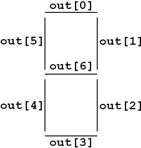
The bits of out are meant to
control the segments of a 7-segment LED, as per the following diagram:
For each bit of out, the value 0 causes that segment of the LED to be lit, and the value 1 causes that segment of the LED to be off. This is opposite from the LED_RED devices you used in Lab 1. Complete the code so that the value of out returned by hexdigit generates a human-readable picture of the input value on the 7-segment LED.
Remember that each output value must be defined for each combination of input values (usually by specifying a default value before the if statement). Also remember that multi-bit values are specified with the most-significant bit on the left. E.g., out = 7'b0110000; is shorthand for:
	out[6] = 1'b0;
	out[5] = 1'b1;
	out[4] = 1'b1;
	out[3] = 1'b0;
	out[2] = 1'b0;
	out[1] = 1'b0;
	out[0] = 1'b0;
Note the following two lines in top:
    hexdigit u1 (SW[3:0], HEX0);
    hexdigit u2 (SW[7:4], HEX1);
These lines are not executable statements. Rather, they specify that the circuit includes two instances of your hexdigit module (arbitrarily named u1 and u2), with both instances of hexdigit operating continuously and at the same time. Each instance of hexdigit continuously receives as input a set of values from the switches (SW). The output from each instance of hexdigit is continuously fed to one of the 7-segment LEDs (HEX0 or HEX1).
Compile, download, and test your circuit. You should see two of the 7-segment LEDs display a picture corresponding to the values of the switches. If the wrong picture is displayed, fix your code in hexdigit and try again.
Create a new Verilog file called difference.v and add it to your project. difference.v should contain a module difference that computes the absolute value of the difference of two 4-bit input values and produces a 4-bit output. Your code will be similar to the variations you wrote in Lab 1. difference will get its inputs from two input parameters (similar to hexdigit's input parameter) and output its result to a parameter.
Next, you will modify top to compute the difference between SW[7:4] and SW[3:0] (using your difference module) and display this difference onto HEX2.
First, draw a schematic picture of your new top module. Draw wires to show how information flows between the various modules, and label each wire. For example, the inputs to difference should be SW[7:4] and SW[3:0], and the output will be a new variable, which you could call diff.
Next, modify top to implement your new schematic. You will need to include an instance of your difference module; the code provided in top.v shows how to include instances (of hexdigit). You will also need to declare any internal wires (such as diff). Declare these wires in top after the declaration of the top module, e.g.:
wire [3:0] diff;
Before you arrive in lab, you should:
Remember that you can create and edit Verilog files with any text editor, i.e. you need not use Quartus's text editor. If you'd like to use Quartus on your personal PC, you can download it for free from Altera.