The camera controller handles the low-level details of communicating with an attached video camera. The camera controller is implemented in camera.v, camera_fifo.v, YCbCr2RGB.v, and MAC_3.v. You will also need i2c_config.v, which configures the DE2-115's video decoder chip, the Analog Devices ADV7180.
The camera controller captures images from an attached video camera and stores them in the video memory of the VGA controller. The image is saved to the video memory, starting at the coordinate of the upper-left corner of the image (camera_x, camera_y). Each value in video memory stores the color of a pixel: bits 14-10 specify the amount of red; bits 9-5 specify the amount of green; and bits 4-0 specify the amount of blue (this is known as 15 bit RGB).
The dimensions of the captured image depends on the scale factor:
Any portion of the captured image that appears in the visible portion of the video memory ( (0,0) to (639,479) ) will appear immediately on the VGA monitor. You can also capture images to off-screen memory, e.g., (0,480) to (639,959). This is useful if you want to analyze the image without displaying it, or if you want to transform the image before showing it. You can read the image after it has been captured to video by using the VGA controller.
camera_command and camera_response implement the standard I/O protocol. The command parameters are camera_x, camera_y, camera_scale, and camera_mirror. The command tells the camera controller to capture an image to a rectangle in video memory. The upper-left corner of the rectangle is (camera_x, camera_y), and the size of the image is specified by camera_scale. The camera_mirror parameter determines whether the controller captures a normal image (camera_mirror=0) or an image that is flipped horizontally (camera_mirror=1).
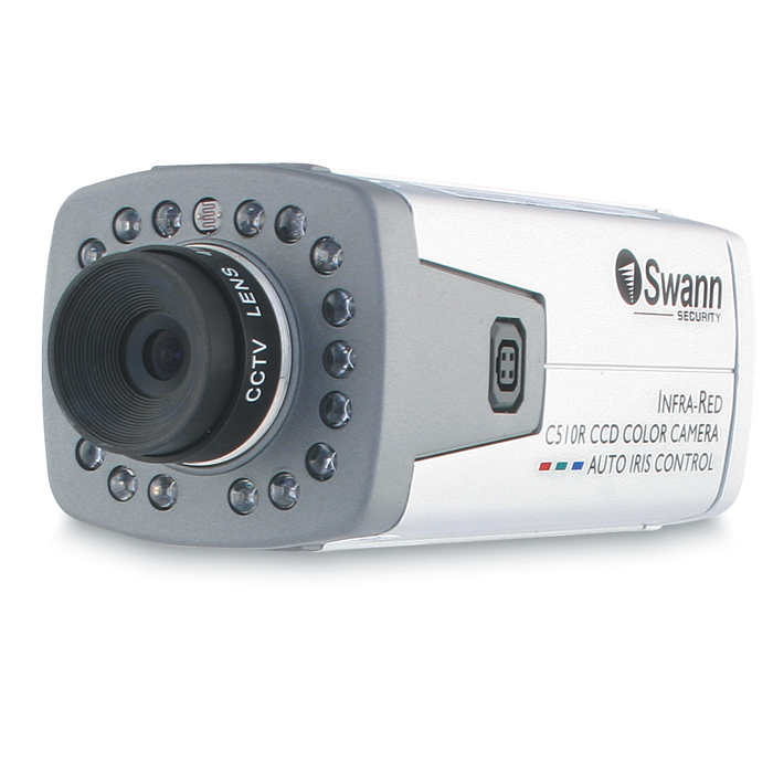
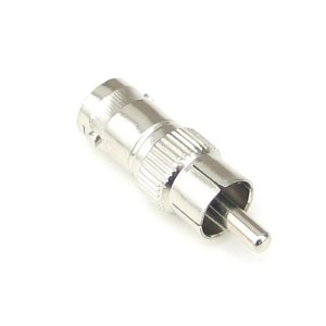
On the DE2-115 board, plug a Swann C510R Professional CCD Security Camera into the round VIDEO IN connector via a BNC to RCA adapter.
ase100 simulates the camera controller accurately enough for you to test your device driver and to run assembly-language programs. If your computer has a webcam or video capture card, ase100 can read images from that device.
If ase100 cannot access a video input device on your computer, it reads images from a video stream stored in a vid100 file. To create a vid100 file from a standard-format video file (e.g., AVI or MPEG), run the following command:
~pmchen/Public/vid100 video-fileReplace video-file with the name of the video file that you want to convert into vid100 format. The resulting vid100 file will be in video-file.vid100. Warning: vid100 files store uncompressed video, which takes a lot of space (9 MB for each second of video). You can find an example vid100 file at ~pmchen/Public/campus.avi.vid100
Write a device driver for the camera controller that a program can call to capture an image to the video memory at a specified (x,y) coordinate. Then, write a program that continuously captures images (of scale 2) to the video memory. The captured image should "bounce" diagonally around the screen: the first image should be captured to (0,0); the second image to (1,1); and so forth. When a corner of the image hits an edge of the screen, switch directions. E.g., if the image is moving down and to the right, and the lower-right corner of the image hits the lower part of the screen, change the direction to up and to the right.