You may not choose the PWM controller for Lab 7.
The PWM controller handles the low-level details of creating a PWM or (Pulse Width Modulation) signal. The PWM controller is implemented in pwm.v.
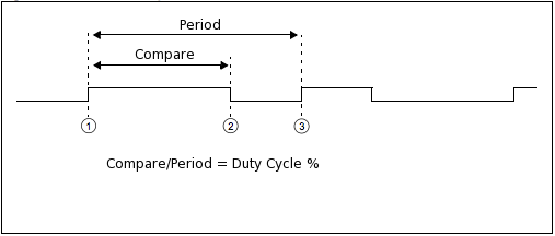
PWM is used to create an approximation to an analog output, by simply
using digital output. It does this by modulating a signal very quickly,
and has that signal on for a certain percentage of time. So, the signal that
appears is the digital high voltage value X the percentage of time the signal is high.
ie) for a 5V logic line, if the signal is high 60% of the time
it will actually look like 3V.
pwm_command and pwm_response implement the standard I/O protocol. The command parameters are pwm_compare and pwm_period. There are no response parameters.
The PWM controller creates a signal that is high for pwm_compare number of ticks and is low until pwm_period ticks. The duration of each tick is specified by the clock that is used, which in this case is the 100 MHZ one. So, each tick is 10ns. If you want longer duration ticks, you need to modify the clock input to the pwm module.
So, to create a 100ns signal that is high for 80% of the time, simply set pwm_compare to 8 and pwm_period to 10.
To get started with the PWM controller, you'll need to change your top.v to this new top.v. You also, need to download pwm.v and add it to your project. Then you should be able to recompile your project and you'll be all set.
On the right of the DE2-115 board, there are 2 columns of GPIO pins.
(General Purpose Input/Output). These work to receive digital input
and send digital output. The top.v that we provide you with
uses GPIO[2] to send the pwm signal, you can change that to whatever you want. Note that GPIO[2] is actually pin 3 in the figure below.
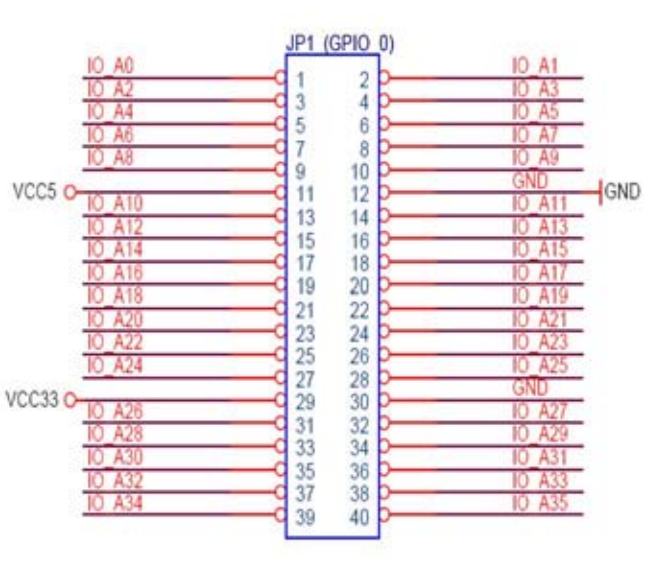
Also, note that pin 11 is 5V pin 12 is ground, 29 is 3.3V and 30 is ground.
You can power a servo directly from your board by plugging the black wire into pin 12, and the red wire into pin 11. You should then connect the yellow wire to pin 3 / GPIO[2] to use your pwm output. To move this servo, you need to send a signal that has a 20ms period. You'll want the compare somewhere between 0.7ms and 2.3ms, this would get you about 0 degrees and 180 degrees respectively, when using the servos. You might want to play around with the exact numbers until it behaves exactly how you want, ie) the above numbers might get you 175 degrees depending on your servo.
To use a motor, you'll need to use something called an H-Bridge. If you want to get an in depth understanding of the one we're using look here or look up a tutorial on using H-Bridges online. To simply move a motor in one direction connect pin 12 and pin 30 to the ground pin on your H-Bridge, also connect this to the CSA pin on your H-bridge. Then connect pin 29 (3.3V) to the VLS (Logic Voltage) on your H-Bridge. Connect Out1 and Out2 on your H-Bridge to the 2 different wires of your motor. Connect the VS (Supply Voltage) pin on your H-Bridge to some voltage supply, for the small motors you can just use pin 11 (5V) on your FPGA.
The remaining pins are the fun ones: EN, IN1, and IN2. EN dictates whether the H-Bridge allows current to flow, so think of it as an on/off switch. You'll connect this to your pwm pin (pin 3 / GPIO[2]) to vary it's output. IN1 and IN2 change the direction of the motor. If they are the same, then the motor will be put into a fast-stop state. While they are different they will go in a certain direction, if you invert them from that position, they will go in the opposite direction. So if you just wanted your motor to move in one direction, you could wire IN1 directly to VLS and IN2 to ground.
The new ase100 will ignore any PWM commands, so to accurately test the PWM module, you will have to do it off of the board. The old one will most likely crash. To use the new one, download it here. Note that only the Linux 64-bit ase100 is updated.