SPI controller
You may not choose the SPI controller for Lab 7.
The SPI controller handles the low-level details of communicating with a device using a protocol known as SPI. The controller is implemented in spi_wrapper.v and spi.v.
spi_command and spi_response implement the
standard I/O protocol.
The command parameter is spi_send_data. There response parameter is spi_receive_data.
To get started with the SPI controller, you'll need to
change your top.v to this new top.v
You also, need to download spi.v and add it to your project, along with spi_wrapper.v. Then you should be able to recompile your project and you'll be all set.
On the right of the DE2-115 board, there are 2 columns of GPIO pins.
(General Purpose Input/Output). These work to receive digital input
and send digital output. The top.v that we provide you with
uses GPIO[4] for miso, GPIO[5] for mosi, and GPIO[6] for sck. You can change that to whatever you want. Note that GPIO[4] is actually pin 5 in the figure below.
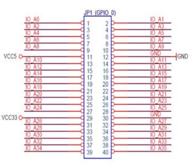
Also, note that pin 11 is 5V pin 12 is ground, 29 is 3.3V and 30 is ground.
The new ase100 will ignore any SPI commands,
so to accurately test SPI communication, you will have
to do it off of the board.
The old one will most likely crash. To use the new one,
download it here. Note that only the Linux 64-bit
ase100 is updated.