Our goal was to create a mobile project that could evade objects using multiple distance sensors, as well as provide feedback through an LCD screen.
High Level Design
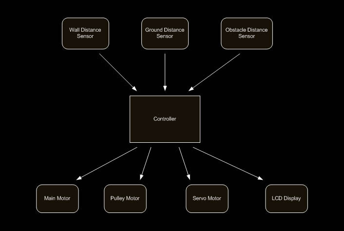
The Spider carries the majority of the equipment, including a microprocessor, an LCD screen, motors and a sensor, as well as the egg itself. The Spider is attached to a string spanning two walls, which it can detect with its sensor.
The Egg hangs down from the Spider on a pulley system controlled by the Spider. It is smaller with two sensors to detect the ground and obstacles.
The Spider moves back and forth on the string, turning around when it detects a wall. It also moves the Egg up and down on the pulley trying to keep it from hitting obstacles or running into the ground.
Member Task Distribution
Hardware Design
To implement timing we used an up-counter in the MPC555 MIOS module (Modular Input/Output System) that used a scaled version of the system clock. We used it by write a zero to the counter and wait for it to count to the correct value.
We used a PIT (Periodic Interrupt Timer) in order to keep a tempo for the logic control flow. We set this timer to throw an interrupt every 1/10th of a second.
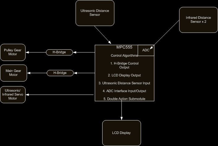
For movement we primarily used gear motors since they had the highest torque. To turn on and off the gear motors, as well as control their direction, we used H-Bridges that were located on the bread board..
For the Spider to detect the distance to the two walls it used an ultrasonic distance sensor. The ultrasonic distance sensor responds with a pulse of a particular width, which corresponds directly to the distance to the wall. In order to measure this width we used the MIOS Double Action Sub Module. This module uses two registers and a counter. When it detects a rising edge it will put the value of the counter in one register, and when it detects a falling edge it will put the value in another register. The difference between these two registers gives us the width of the pulse.
The egg carries two infrared distance sensors. The infrared distance sensors continuously output a voltage. The MPC555 has two built-in ADC modules called QADC (Queued Analog to Digital Converter) that we used in order to read the values of these sensors. Each QADC module has its own 64 line Command Word Table and 64 Line Results table. Each command word corresponds to a result line. We filled the command word table with commands to read a particular sensor and set the QADC to continuously loop through the table. This allowed us to read the entire table and average it to get a more stable result. We did this for each QADC.
The ultrasonic sensor on the Spider and the infrared obstruction sensor on Egg each needed the ability to change direction since the Spider would be moving back and forth across the strings. To accomplish this we used two servo motors on which we mounted the sensors to. To control the servo motors we used the MIOS PWM sub modules. These modules allow us to control the period and pulse width on an output pin. One PWM module was used for each servo.
To control the LCD screen on the side of our project we used the GPIO (General Purpose IO) module. We also used a few pins of this module to communicate with the H-Bridges and the ultrasonic distance sensor (to initiate a reading).
Software Design
|
Software Control Flow
|
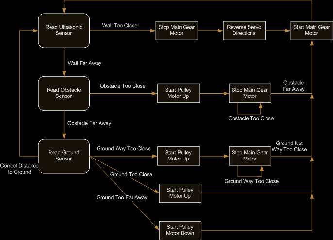
We also encountered several interference issues caused by IO and the gear motors causing the servos to turn. This was resolved by carefully placing wires such that they were far apart from one another (or having spacer wires between on ribbon cables), and allowing the servos to be on all the time.
A significant amount of time was spent debugging power issues. As the main gear motor turned on and off, we saw large shifts in voltage throughout our system, causing the ultrasonic sensor to trigger early. To handle this we decided to modify our algorithm to turn off the gear motor before sampling the ultrasonic sensor. This seemed to help a small amount but did not fix all of our problems. Later, when both gear motors were turning on and off it was causing the voltages to swing so much as to reset the MPC555. The final solution consisted of connecting 3 millifarads of capacitance to the 12V and GND rails.
Conclusions
Once the MPC555 is up and running it is a great processor to work with. It has plenty of useful features to take advantage of once a student learns how to use them.
Axiom (PB0555)
Jameco (Electronics)