Contents:
- Introduction
- High Level Design
- Member Task Distribution
- Hardware Design
- Software Design
- Mechanical Design
- Results and Conclusions
- Media
- References
- Acknowledgements
Introduction
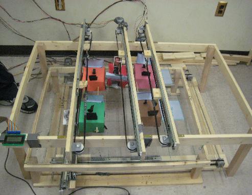
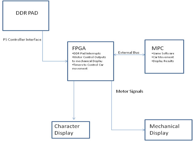
Our group implemented the game Frogger (Brehobber) using a mechanical display. We created the game using a DDR pad to control the X-Y movement of the frog and drive it through the traffic. We used Stepper motors with H-bridges to move the cars and the frog. The entire grid was mapped in software which was used to detect a collision. We also interfaced with an LCD character display to display the status of the game.
High Level Design
To construct the X-Y table for the movement of the frog, we followed the instructions provided on the following webpage:
http://www.instructables.com/id/Low_Cost_Hobby_Servo_XY_Table/
The X-Y table was then calibrated through rigorous testing, and mapped to software which was used to detect the collision.
Member Task Distribution
Varun Tomar:
- DDR Pad Timing and Hardware
- Character Display Hardware
- Mechanical Design
- Interrupt Design
Jad Yacoub:
- Car Movements and timers
- Hardware Design
- Software and Collision Detection
- Calibration
Sunil Sadasivan:
- Circuit Design (Hbridges, DDR Signal Filtering)
- Stepper Motors
- Software
- LCD Interfacing
Chris Mikulski:
- Mechanical Display Design
- Motor Hardware Design
- Character Display Hardware
- Calibration
Hardware Design
Timers:
We used a clock divider to divide the bus clock and create a slower clock running @ 33 Hz. This clock was used to generate an interrupt that controlled the movement of the 2 out of 3 rows of cars.
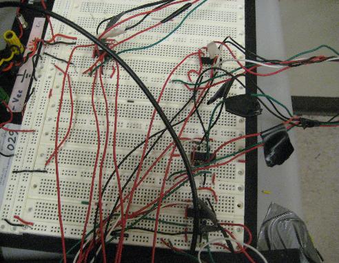
Stepper Motors with H-Bridges:
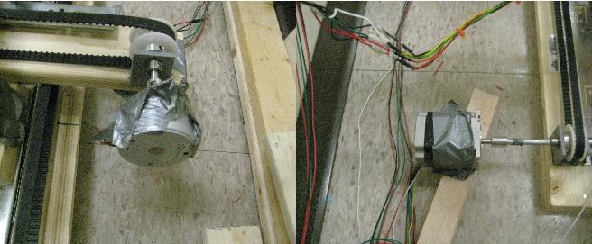
In this project we used 5 stepper motors. Four 55M048D2U steppers, and 1 NEMA23 stepper motor. For each motor, we needed to create a controller which switches patterns of ground in a particular order to move forward or backward. We used H-bridges to pull up the voltage required by the steppers, and used the 4 transistors on each hbridge to switch the ground patterns. (See References) for the patterns. Below is each hbridge for the 4 55M048D2U steppers.
DDR Pad:
We needed to work with six pins on the play station controller: DATA , GND, VCC, ATT, CLK and CMD. DATA needs a 100k PULL-UP resistor. In researching, we found a previous 373 project (DDR-A-MOLE) gave us some great links to get started. We used the same DDR Pad as this project, but we found that the description this group gave on how to interface with the pad was flawed. This group did not use the CMD and held the ATT signal active low for much shorter time than we needed to. After having problems for a couple days with this, we decided to interface with the pad using the traditional CMD signal. We pulled ATT low every .8 milliseconds. This signal stays low for over 32 DDR clk cycles. The DDR Clk runs at about 156 kHz. The buttons are active low. We found that we only needed to drive the clk when the ATT signal is low. For debugging purposes, the ps2 controller will only drive data on the falling edge of the clk and can be latched on the rising edge. This enables us to keep the clk signal high after every byte of data, so that we can easily distinguish the bytes. See the references for a great link of how we found this possible (See References). After ATT is pulled low, we send 0x01 as the first byte on the CMD signal, then we send 0x42 as the next byte. The data will then follow after these commands. The DDR-A-Mole group did not do this and we were unsure of how they got the pad to work without this signal.
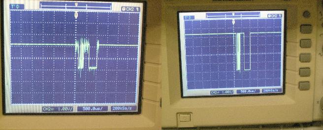
A major issue is that all signals will be driven on to the data line. This means that we needed to set up a comparator circuit to set up a threshold of high versus low. Below is a before/after comparison of the signal quality.
We also buffered all input and output signals by running them twice through inverters.
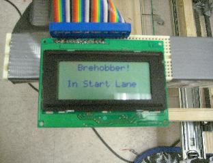
We operated the 2-line character display in 8-bit mode and initialized it in hardware by following the algorithm step-by-step provided in the above mentioned link.
(See References)
Software Design
Once the program starts running, the first task was initialization which was mostly written in assembly. After initializing the timers and interrupts, we then initialize the location of the frog and the cars to their start position. This is done so we know exactly where the frog and car positions are. The next step was to enable the specific interrupts for the DDR Pad and timers for the motors. The interrupt handlers in assembly were used to move the stepper motors and they would then call C functions which update the location of the cars and frogs and make sure no collision occurred. When the game is over, we wait for the start button interrupt from the DDR Pad which starts the initialization sequence once again.
The hardest part here was making sure that the software was in sync with the actual game and that it was calibrated correctly. A lot of time was spent deciding on when to move the car and the frog and when do they make it to the next square. We ended up giving a slight advantage to the user.
Mechanical Design
In total, we used roughly 67 feet of wood. Our mechanical system has three major components: the top table, the bottom table, and the x-y table. Below, we list some facts/specifications regarding our mechanical construction:
- The Top Table
- Purpose: To hold in place the pulley systems for the cars
- Note: We used the same pulley system for the cars, as we did to give the frog movement in the x direction (We simply replicated this system three times because we had three rows of cars).
- When we attached the pulley system to the top table, we turned the pulley system to the side. This was to reduce “blind spots” for the user (Please see section titled “Reducing Blind Spots” for details)
- We used brass L-brackets to attach the pulley system to the table
- For details on the pulley system, please refer to the Instructables article, created by user CarlS (See in references below)
- Dimensions: 48x29 inches
- Constructed using 1x3 wood
- The Legs
- 15 inches in length
- Constructed using 2x2 wood
- The Bottom table
- Purpose: To hold up the plexiglass
- Dimension: 36x29 inches
- Constructed using 1x3 wood
- The Legs
- 8 inches in length
- Constructed using 2x2 wood
- The X-Y Table
- Purpose: To give the “frog” movement
- Dimension: 42x31 inches
- Constructed using 1x4 wood
- Based off of Instructables article by CarlS. See in references below
- The differences
- The article uses servos, while we used stepper motors
- We ran out of shaft collars, so we improvised a little bit by using a washer and a tie-wrap to hold the bearing in place. Surprisingly, this worked pretty well.
Reducing Blind Spots
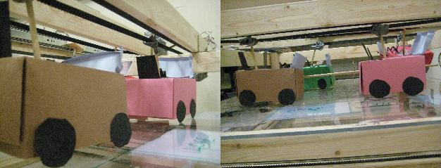
Because the user looks at the game board from the top, we noticed that the pulley system occasionally blocked the vision of where the frog was. We called these areas “blind spots”. To reduce the “blind spots”, we turned the pulley system for the cars on its side. Furthermore, we made sure to make the cars and the frog big. At the end, the “blind spots” weren’t as big of an issue as we had anticipated. It was pretty easy to see what was going on from any angle.
Results and Conclusions
Our initial proposal was to use etch a sketch to implement the game, however after initial testing we realized that this won’t work mainly because the board was too small. So we moved to plan B which was building our own display.
We also ran out of ports on the expansion board, because we used 5 stepper motors with H bridges. So we were limited in the number of external devices that we could interface to.
Building the mechanical display was time consuming, but overall it was a success. The main conclusion here is when in doubt use duct tape.
Media
References
- Playstation 2 Controller Interfacing:
- X-Y Table Construction:
- Stepper Motor Documentation
Acknowledgments
Our team would like to thank Instructables user, CarlS, for his article titled, “Low Cost Hobby Servo XY Table”. His article helped us a lot in creating the x-y table. He also has some cool projects at http://www.teletoyland.com/
Also, we would like to thank our lab instructor, Matt Smith, for his advice throughout the project.