Software Design
Timing
For our project we used mostly software timers.
Since our project had a very sequential routine, we decided not
to use interrupts. Each
action simply called the next function which would begin the next step
of the toppings assembly line.
For the distance sensors, keypad, character
display, thermistor, solenoid, and whipped cream gear motor we had to
implement wait states. To
implement these wait states we used the timers to count to a certain
number, and upon reaching that number reset.
A timer was needed for all of the components that
used the ADC. In our project
we had three components using the ADC: the
long range distance sensor for the linear transport, the short range
distance sensor for the sprinkle refill, and the thermistor.
In order to get correct data from the ADC you have to wait 200
microseconds after the conversion, otherwise your data will not be
correct. The timers were
used so we could sample at the correct time.
The whipped cream gear motor used a timer to
determine how long the whipped cream was dispensed.
The motor, which controlled a lever to tip the whipped cream can,
was turned on in the clockwise direction for a few seconds to dispense
the whipped cream, and then switched in the reverse direction and turned
off when the whipped cream was done dispensing.
The amount of time that the motor was left on was determined
using timers.
The character display had many different timing
constraints. In order to
meet the setup and hold time constraints between each command to the
display, we implemented a wait function that was called each time the
character display control registers were written to.
The keypad worked by writing to the columns and
reading from the rows. Since
the keypad is a mechanical device, we implemented a 1 ms wait state
between the write and the read to account for any glitches that may have
occurred as the button was being pressed.
The only component that we used a hardware timer
for was the servo. For this
device, it was important to specifically set information like the duty
cycle. We found this to be
easy in hardware.
Issues
One of the issues that we ran into with software was determining how
high the timer counted to.
When the timer number was sampled you would never know what number it
was at. This created a
problem because for example if we wanted to count to 40 but when we
sampled the timer it was already at 50 and it only counted up to 64 then
we would not necessarily count to the correct number.
To work around this we had to figure out the range that the timer
counted from. We observed
that the range was from 0 to 64.
Once we knew the range, we had to come up with logic to account
for the uncertainty of the first number sampled.
Another issue we encountered was the timing for the
character display. The setup
and hold times are very complex and tricky, especially while
initializing the display.
This proved to be the most difficult issue with the character display
and took an unexpected amount of time to debug.
Once the timing was debugged we also ran into problems with
writing half words in assembly rather than words, because the processor
was putting the data in the incorrect bit positions.
Programming Language
For our project we used mostly assembly language.
For the components and the type of functionality we used them for
we found it easiest to use assembly.
We did use some C code to write a couple functions that included
more mathematical algorithms, such as our function to calculate the
median of a set of numbers.
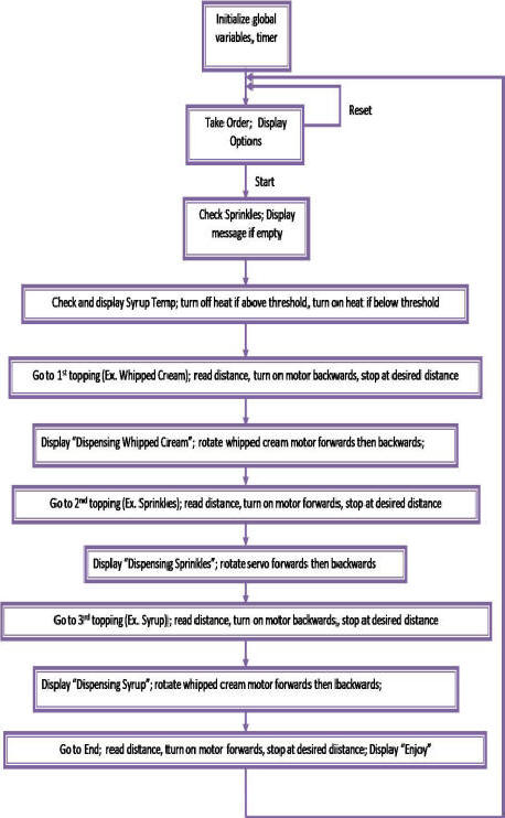
Software Flow Chart