Members | Introduction | High Level Design | Task Distribution
Hardware Design | Sofware Design | Results & Conclusions | Media | References | Appendix
Brad Freyburg
Neal Parker
Edwin Tay
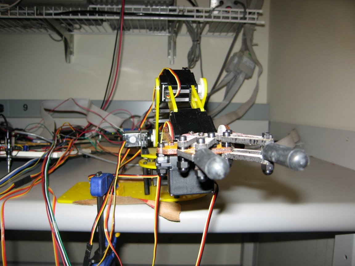
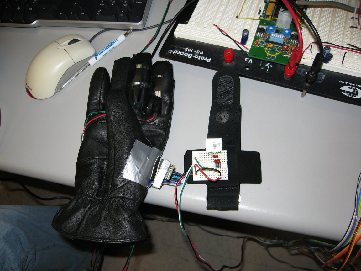
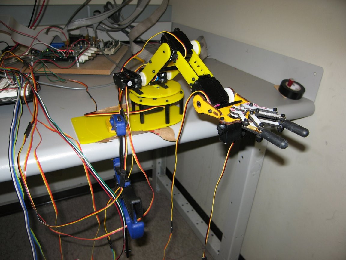
The initial aim of our project was to have a robot arm mimic a user's actual arm movement in real time. A combination of accelerometers and pressure sensors were incorporated into a glove and used to control the 5 different servos in the robot arm. A Nintendo 64 controller was also used to both provide a platform to characterize the movements of the robot arm, as well as a different interface should a user decide against using the glove. We had originally planned to use an LCD display as well, but quickly found it to be superfluous since the existing LED and hex displays were perfectly capable of handling our display needs. We also had to simplify our mapping of the user glove movements to the robot arm's movements due to a lack of time.
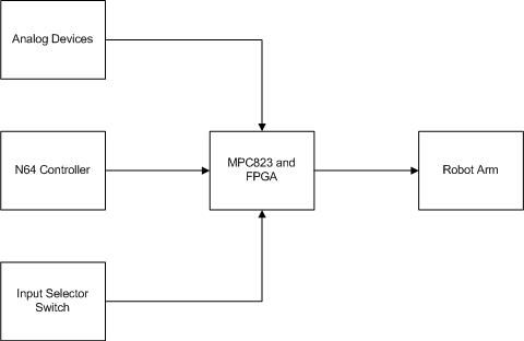
Our overall design was pretty straightforward. There were 4 types of input sources, the N64 controller, the two accelerometers, two pressure sensors, and a slide switch. The only output of our design is the servo controlled robotic arm. We used the ADC to convert the data of the pressure sensors and accelerometers to a value that could be used for the PWM generation. The functions of each of these subcomponents is listed below.
Brad - N64 Controller hardware interfacing
Neal - Pulse width modification for servos, N64 software interface
Edwin - Accelerometers, pressure sensors, mapping of arm movement to servo positions
Pulse Width Modulation
The generation of the pulses was all done in hardware. Each of the 5 servos has its own respective PWM generation module and memory-mapped register. The module consists of a counter, flip-flop, and comparator. When one of the memory-mapped registers was written to, the data from the processor would be latched into the flip-flop. The counter then starts to count, setting its output high, until it reaches the value latched in the register. When this value is reached, the pulse goes low. The counter continues to count and generate this same pulse repeatedly every 20 milliseconds until a new value is written to the servo.
The servos accept pulses between 0.5 ms and 2.5 ms, where a pulse widtch of 1.5 ms is the servo's neutral position. In order to generate these pulses, the comparator accepted values between 0x1388 and 0x61A8 (0.5ms and 2.5ms, respectively), and divided the bus clock to generate the pulses.
N64 Controller
The N64 controller communicates with the demo board over a single serial data line. This line is bi-directional and asynchronous, the clock is encoded in it like Manchester encoding. Button status and the location of the analog stick is acquired by polling the device with a specific pattern, we send this pattern every 400ms. After the pattern is sent the controller replies with 32 bits of data which is sent into cascaded shift registers. The output of the shift registers is placed bank of D flip Flops. This completes the serial to parallel conversion. In this way software can safely access the controller independent of timing constraints.
Analog Devices
The hardware for the ADC was very similar to the design in Lab 8, with changes made to account for the new interface with the project expansion board.
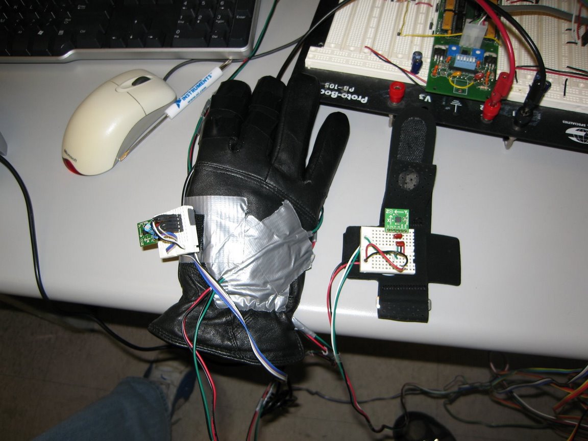
The accelerometers were very sensitive to changes in their Vcc, so we had to perform some voltage division to step the Vcc down to 3.3 V from 5.0 V, since the power supply was already being used to power the other devices, and the power lines from the expansion board were not reliable enough.
The pressure sensors changed their resistance with pressure, so a simple voltage divider also had to be built for them in order to measure the change in their resistance.
N64 Controller
To determine which buttons were being pressed, the complete 32-bit N64 data was read from the memory-mapped registers and parsed in C, using the appropriate shifts and masks. For example, if Left on the directional pad was pressed at the same time as the A button, we moved the arm left and closed the claw. A press of a button corresponded to a 1 degree change in motion for the servo. For the analog stick, as long as the stick was off-center, we moved in that direction at a constant rate. There was no idea of a 'hard' left or a 'soft' left, just left.
Analog Devices
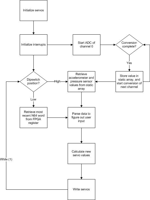
The AD_EOC signal from the ADC was inverted and used as the IRQ1 signal to the processor. IRQ1 was configured as an edge-sensitive interrupt, and the handler was responsible for retrieving the converted digital value from the ADC, saving it in a global array, and starting the conversion for the next channel. In this way, the conversion of the analog values was continuously being done in the background, and it greatly simplified the software processing.
Accelerometers
We also used a threshold system to translate the accelerometer readings to servo values. Since the analog values were continuously being converted and stored in memory by the interrupt handler, figuring out the tilt of the accelerometer merely involved accessing the correct value in the global array. If this value was below a lower threshold, we decremented the respective servo's angle, and if the value was above an upper threshold, we incremented the servo's angle. This translation caused the servo to move at a constant rate once the accelerometer's tilt went above or below the thresholds.
We originally wanted to implement direct control of the arm (if you put your arm at a 45 degree angle, the robotic arm moved to a 45 degree angle), but the math to do this was complicated and we did not have enough time to implement it. Scaling the change in the servo's angle with the size of the tilt also proved to be difficult due to the twitchiness of the converted accelerometer readings, which caused the servos to move unpredicatably even when the respective accelerometer is at the neutral position.Pressure Sensors
To provide a realistic feel for the claw's movement, we characterized the movement of the claw servo and provided a linear mapping between the value of the index finger's pressure sensor and the tightness of the claw. With no pressure on the pressure sensor, the claw would be open at its maximum width. The harder the pressure sensor was pressed, the tighter the claw became. The user was therefore able to completely control how tightly the claw was gripping an object by using the pressure sensor.
The middle finger's pressure sensor functioned on a threshold value. All 5 of the servos were reset and returned to their neutral positions once the pressure on the sensor exceeded the threshold. This allowed the user to easily get themselves out of a jam while learning to control the arm with the accelerometers.Servos
After all necessary values in the global ADC array were checked, and all calculations completed, we then wrote the new servo values to the memory-mapped registers controlling the pulse-width to the 5 servos. This worked well to update the robot arm's movement.
The results of our project were slightly below our expectations. Having the robot arm mimic the actual motions of the user's arm required fairly complicated math, so we had intended to implement a coordinate system for mapping the user accelerometer inputs into servo values. We ran into some trouble devising a way to do this, and were only able to come up with a formula in the last few days, but we judged that it was too late to implement it in software, since we had to figure out a way to perform inverse cosines and square roots using fixed-point calculations. We might have been able to implement it with another week on the project, since the inverse cosines could have been done using a lookup table, and the square roots done with a simple recursive algorithm.
We were also originally planning to use piezeoelectric strips to sense the movements of the fingers. However, the strips turned out to measure the change in strain rather than strain itself, so we substituted them with the pressure sensors instead. We feel that the pressure sensors ended up being a better choice anyway, because they provided a very sensitive and responsive interface for the claw.
We are satisfied with our project, despite not meeting all our initial goals. While there is a slight learning curve to controlling the arm with the accelerometers, it is relatively easy to produce the desired motion once a user becomes familiar with the device. The only servo movement that wasn't very intuitive is the movement of the elbow joint on the arm.
Controlling with accelerometers - http://www.youtube.com/watch?v=UL4dGpKc6AY
Controlling with Nintendo 64 - http://www.youtube.com/watch?v=ofvXeTMXnwY
Attempt at catapulting - http://www.youtube.com/watch?v=0b3GLf0zY88
Servos:
Nintendo 64 Controller:
http://instruct1.cit.cornell.edu/courses/ee476/FinalProjects/s2002/jew17/lld.htmlm
http://www.eecs.umich.edu/courses/eecs373/Labs/devices/373%20N64%20support%20doc.pdf
Calculations for mapping of coordinates to servo values