
| Home |
| How it works |
| Parts |
| Media |
| About |
Parts
Smart Fan is composed of an EECS 373 I/O board with Motorola MPC823 processor and FPGA connected to two ultrasonic rangers, two servos, two computer processor fans and a Nintendo 8 controller pad. For the ultrasonic rangers, servos, fans, and Nintendo 8 controller, hardware was implemented and programmed onto the FPGA to interface with the devices. Xilinx was the tool used to design the hardware logic.
Ultrasonic Rangers
To use the ultrasonic rangers, a pulse is sent to the device which initiates the ultrasonic ranger to send out a high-frequency (ultrasonic) signal. The high-frequency signal will reflect from the objects in its path and returns to the ultrasonic ranger. The time between the initiating starting pulse and the returning echo is measured to determine the distance of the object.
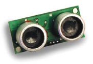
The Smart Fan's hardware is designed to constantly send a pulse to the ultrasonic rangers. While the ultrasonic sends out the high-frequency signal, the hardware uses a counter to count the number of processor clocks until the returning echo is received. Once the echo is received, the counter stops and the number of clocks counted is stored into a 32-bit register. A device, such as the MPC823 processer, can then read this register at any moment in time and the most recent number of counted clocks will be present. This hardware design greatly reduces the complexity of the Smart Fan's software since interrupts will not be required to signal valid ultrasonic ranger data, but instead any simple register read will yield up-to-date counts.
Servos
Pulse width modulation is used to interface with the servos. Depending on the pulse width of the signal received, the servos will rotate to a specified degree. Sending a square wave to the servos will lock the servos into the specified degree corresponding to the pulse width of the square wave.
The Smart Fan's hardware contains a pulse width modulator that sends a square wave to the servos. The pulse width of the square wave is regulated by a register in the hardware. Writing a different value into the register will cause the pulse width to change. Longer pulse widths are achieved by writing larger values into the register and conversely shorter pulse widths are achieved by writing smaller values.
Fans
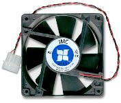
The individual fans of the Smart Fan are simple computer processor fans that turn on and off. External current buffer circuits were built to bridge between the Smart Fan hardware and the fans. +12 V supply is connected to the circuit and a transistor in the circuit acts as a switch that allows or stops the flow of current. When the hardware sends a signal to the transistor, the transistor allows the current to flow through the cirucit and powers the fans.
Nintendo 8 Controller
To interface with the Nintendo 8 Controller, a "latch" pulse is first sent to the controller. On receipt of this pulse, the controller saves the state of the control buttons and direction pad. Eight successive clock pulses are sent to controller which returns the state of each button corresponding to each of the eight pulses.
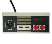
The Nintendo 8 Controller protocol is used by the Smart Fan hardware to interface the controller. The hardware constantly sends the "latch" and eight clock pulses to the controller and saves the returning data into a 32-bit register. Like the hardware of the ultrasonic, the constant data polling greatly simplifies the Smart Fan software and a simple read of the 32-bit register will yield the most up-to-date state of the controller.