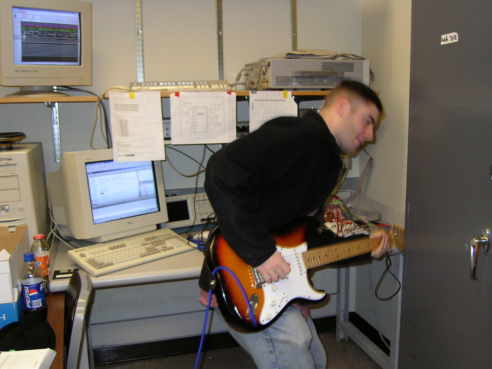
Jared rockin it
EECS 373 Final Project: Guitar Effects Syntehsizer
by Jared Chenkin and Chris Hsiong
| Introduction |
Software Design
The main elements of our project were all, ultimately, conrolled by the software. The effects processing was a main component of the software. It ran in a loop inside of our main assembly program, took latest data from the ADC, checks the state of the effects selection and processes the proper effect. It keeps the past 500 samples in a circular buffer for some of the delay-based effects such as chorus and flange. Distortion was implemented simply by clipping the wave at an arbitrary frequency: any freqency above this clipping frequency was simply change to the value of that frequency. For the echo, each sample was kept in a separate echo buffer so that the amplitude of the current wave would be added to the diminished amplitude of a previous wave. For the chorus and flange effects, a delta function was created that generated values based on a triangle wave. This value, determined by the current index value, were used to index into the buffer of previous samples. This previous sample was then added to the current sample to create the chorus effect. Before the effect can be sent out, though, it needs to be put through an Automatic Gain Controller (AGC) which scales it, based upon the current gain, to a value that is between 0 and 65536, incase, when adding our values together, we got one that was higher than the maximum 16-bit value. For the LCD, we used the software to control the appearance and location of characters on the screen. First, the software used timers to go through the 10 step initialization process. Each step was separated by a timer waiting a certain time noted in the specification. Afterwards, it calls the main menu function which displays the welcome screen, holds it for some time, and then displays the first two effects on the screen, awaiting user input. The screen would display a '>' that pointed to the effect currently being pointed to and an '@' next to the currently selected effect. Placing a character on the screen was achieved by simply writing the value of the character according to the character set specified to the Data Register of the LCD. The Nintedo 8 controller was implemented as an interrupt. In the ISR, the value of controller is read, depending on which button is pushed, an input is sent to the C funcion 'mario', which sets the appropriate place of the '>' or '@' signs, changes the menu, and updates the global state variables as approriate. Click here for a flow chart that shows the software processes (visio required) |
| Software Design | |
| Results | |
| Conclusions | |
| Media | |
| Appendix | |
| References |

Jared rockin it