[User-Programmable Haptic MIDI Controller]
Hans Kuder, Dan BudaiContents
Introduction
We wanted to make a general-purpose MIDI controller with functionality largely defined by the user. The controller would provide haptic feedback (force feedback) to the user to simulate various virtual objects for interaction. The controller would use linear sliders and a footswitch to sense user input and provide haptic output. Based on sensed input, the device would send MIDI messages to an external MIDI-capable device (such as a synthesizer, effects processor, or computer MIDI interface).
[ Back to top ]
High Level Design
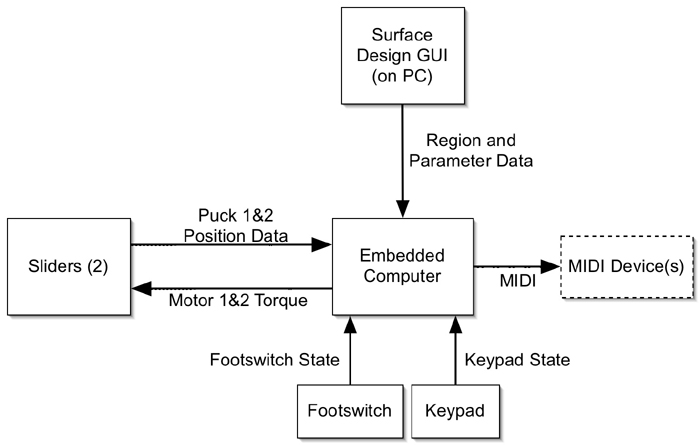
Our design uses two sliders, each with a "puck" for the user to manipulate, as well as a footswitch that can be held on or off or used to trigger events. Both sliders are connected to motors which provide a response force based on the position and velocity of each slider. The sliders and footswitch provide input to an embedded computer which reads in their values and uses the information to generate motor response torques and MIDI messages. The controller also includes a numeric keypad with which the user can select the MIDI channel on which the device sends messages. The user defines detailed functionality by providing the desired MIDI and haptic responses in a graphical user interface running on a separate PC prior to running the system.
Below (click for full size) is a screen shot of the graphical user interface used to configure our device.
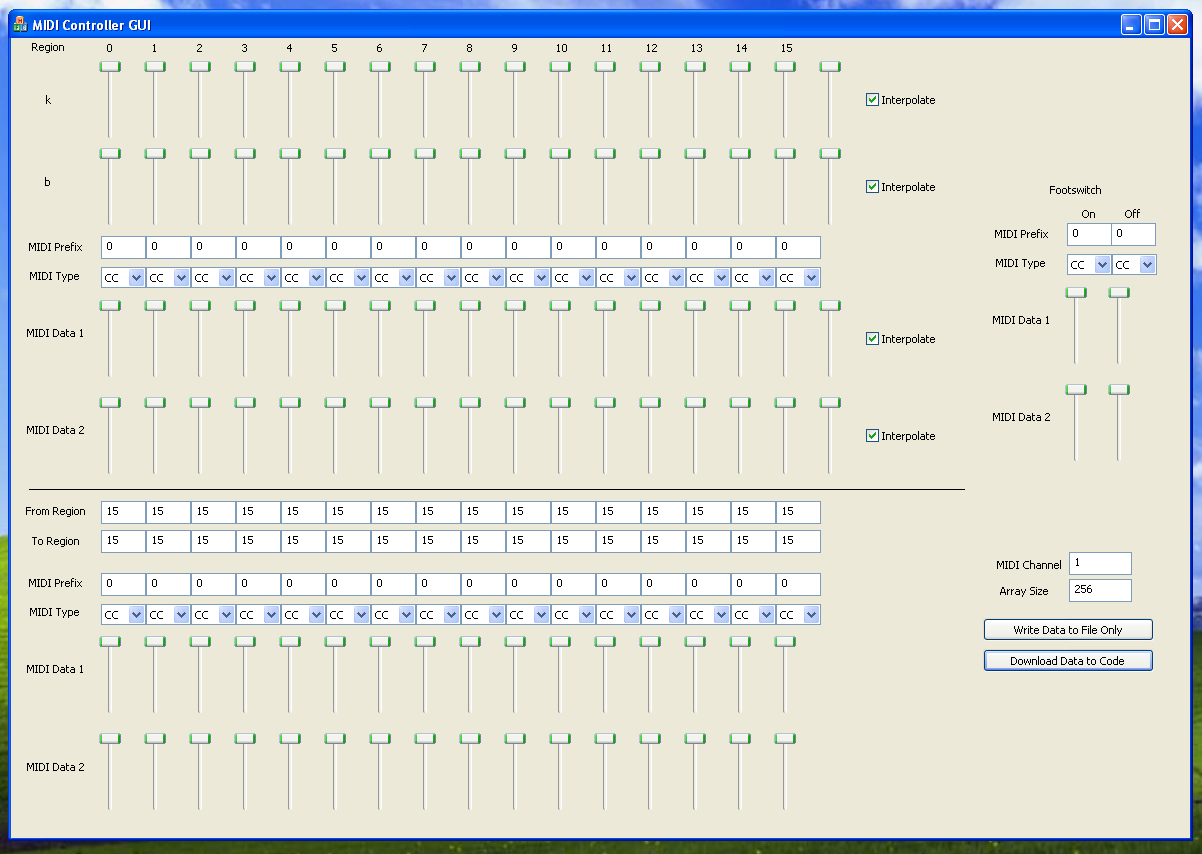
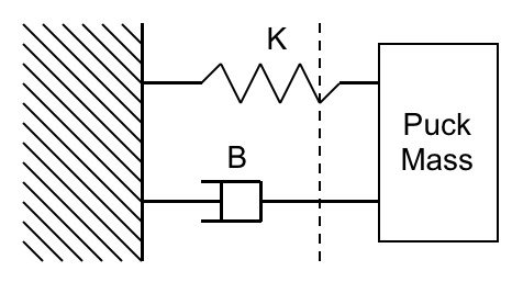
The controller provides feedback to simulate virtual objects as a parameterized spring-mass-damper system, which responds to both puck position and puck velocity. The coefficients used to scale the response can change across the length of the slider. As seen in the interface above, and also in the diagram below, k (spring constant) defines the response to puck position at a certain point along the slider, and b (damping constant) defines the response to puck velocity. The k and b terms for each slider are combined in software and sent to the motors as torque commands.
Each slider is divided into 16 regions, and each region can have independent behavior. Each region has associated k and b values, as well as MIDI message values. The slider sends a region's MIDI messages and response torque continuously when it is in that region. In addition, the user can specify events using this same type of data to be triggered once upon transition between regions. Also, the footswitch can be programmed to trigger MIDI events with its own set of parameters. This allows for flexibility in how the sliders and footswitch behave.
[ Back to top ]
Member Task Distribution
Dan Budai
Setup code, interrupt handling, UART setup, main polling loop, MIDI hardware, footswitch hardware and FPGA logic, keypad hardware and FPGA logic, DAC FPGA logic, surface configuration GUI, overall design
Hans Kuder
Quadrature encoding and decoding FPGA logic, PWM generation circuitry, H-bridge motor control, closed-loop current control, mechanical assembly, overall design
[ Back to top ]
Hardware Design
Please note that our final implementation differed from the initial design discussed in this section. Please see the Design Results section for details.
The sliders are simple sliding keyboard tray mounts, lubricated to provide smooth motion and mounted to a wood base. A "puck" for moving the slider is attached to the top of each. The motor for each slider is mounted to a wheel which transfers torque to linear force along the slider. Puck positions are sensed using two AutomationDirect TRD-SH2500-VD quadrature encoders with 2500 pulses per revolution. These encoders are attached directly to the motor shaft. The quadrature signals are decoded on the FPGA, using 4x decoding (the position count is updated on the rising and falling edge of both quadrature channels) and the position count is stored in a memory-mapped register. A pushbutton on the FPGA I/O board clears the position count register to allow the user to calibrate each slider.
The
footswitch connector connects to a standard electronic keyboard
footswitch (we used a Fatar PS/100), which had only 2 states, pressed
and unpressed. The footswitch acts as a variable resistor, so if
current is sent through it, the voltage across its terminals varies
significantly depending on its state. We connected one terminal of the
connector to VCC = 5 V, and the other terminal to an input pin on the
project expansion board as well as a resistor to ground. We tuned the
resistor so that the voltage seen by the expansion board pin
corresponds to a logical 0 when the footswitch is unpressed and a
logical 1 when it is pressed.
The numeric keypad our design uses (JAMECO 169245) is read in a somewhat indirect manner. While it has 16 keys, it only has eight accessible pins, four for its rows, and four for its columns. By specification, each of its rows must be read separately by sending a logical 1 to it and then reading the four columns on that row. We wrote FPGA logic to handle this polling process so the keypad can be easily read from software as a memory-mapped register. Since a standard MIDI device has 16 MIDI channels, our design reads and uses all 16 keys on the keypad.
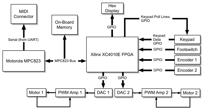
Since MIDI is an asynchronous serial protocol, our design uses the Universal Asynchronous Receiver Transmitter (UART) unit in the Communications Processor Module of the MPC823 processor to send MIDI data. The UART is initialized to a symbol rate of 31.25 kbaud to match the symbol rate of MIDI, and is otherwise initialized for normal serial communication. MIDI data is written to the UART byte-by-byte using drivers written in assembly for this purpose. The UART then sends this data out of the MPC823 board's serial port connection, and simple circuitry on the project expansion board adapts the resulting signal for transmission over a standard MIDI (DIN-5/180°) cable.
Our design incorporates two Anaheim Automation BDR-44-66-12.0V-10600 DC brush motors. These motors are non-geared, which allows their shafts to spin freely when not driven. They draw a considerable amount of current - up to 60A at max torque - so much of our design time was spent trying to switch this much power to the motors without overheating components in the H-bridge. Ultimately, we were unable to create a reliable switching system before our deadline, so we opted to exclude force feedback from our final implementation (see Design Results section).
Control for each DC motor is accomplished with a National Instruments DAC0830 digital-to-analog converter (DAC), Texas Instruments UC3638 Advanced PWM Controller, and switching power transistors arranged in an H-bridge configuration to allow control in both directions. We wrote FPGA logic to handle writing from the MPC823 bus to the DAC. Two14.4V cordless drill batteries are used in series for the motor power source. Since the motors provide force to the user, closed-loop torque control is used to reduce any error resulting from variable load torque. The PWM controller generates a PWM signal with duty cycle proportional to a command voltage sent from the DAC. This PWM signal is used to switch the transistors in the H-bridge. Closed-loop control is accomplished by sensing current through two low-value resistors at the low side of the H-bridge. This current sense signal is sent back to the PWM controller, which includes an inverting error amplifier. The amplified error signal is subtracted from the command voltage to force the motor current to the desired value.
[ Back to top ]
Software Design
Please note that this initial design was
modified for our final implementation. Please see the Design
Results section for details.
Prior to running the system, the user runs a GUI on the PC to which the
MPC823 board is interfaced. This GUI generates data parameters
defining the behavior of the system (such as motor torque parameters
and MIDI message data), storing them as arrays of bytes, and loads this
data into a special “arrays” section of the system
software’s “starts.s” file prior to
compilation. This GUI was written in C++ using the Windows MFC
framework in Microsoft Visual Studio.
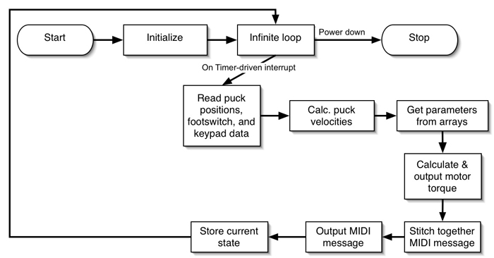
Upon compilation and loading, the system software runs code to
initialize the UART, interrupt handling, and general-purpose timers
(GPT’s). It then enters an infinite loop and waits for
interrupts to do the system’s real work. Our design uses a
single GPT on the MPC823 to generate periodic interrupts; this is
the only interrupt source in the system, and it branches to a single
ISR that handles all of the I/O manipulation for the system. This
way, we have precise control over the rate at which we poll input
devices and output MIDI and motor torque data, which is important for
ensuing that the I/O devices function as desired. We found
experimentally that using an interrupt frequency of 16.67 Hz is
sufficient.
The ISR starts by polling the quadrature encoders and footswitch.
It uses the position read from the encoders to index into the arrays
defining the system’s behavior, and also uses the stored last
positions of the encoders to calculate a pseudo-instantaneous encoder
velocity. It then uses the motor torque coefficients read from
the arrays, combined with the position and velocity data, to calculate
a motor torque, which is sent to the DACs through memory-mapped I/O.
MIDI data is generated using a combination of the encoder, keypad, and
footswitch inputs. The ISR uses the encoder position to index
into arrays defining the system’s behavior, and change in
footswitch state (unpressed-to-pressed, pressed-to-unpressed, or
unchanged) to index into another such array. Then, using the
“MIDI prefix” byte in each array, it stitches together
bytes to send as MIDI messages from the data in the arrays. The
MIDI output channel is determined by the keypad input. The ISR sends
the MIDI messages as a series of three bytes sent to the UART using
assembly drivers written especially for this purpose.
Prior to terminating, the ISR saves the present state (encoder
positions and footswitch state) to memory for comparison with the
present state upon the next instance of the ISR.
Because our software design is ISR-based, we ended up implementing all
of it in assembly. Not a single line of C was ever written.
This ensured proper functionality but made some programming tasks (such
as motor torque calculation) more difficult.
[ Back to top ]
Design Results
Due to time constraints and component availability, we were unable to develop an H-bridge that reliably switched enough power to the motors withoutoverheating. In the course of trying to create working a working motor control system we destroyed several H-bridge integrated circuits and numerous switching power transistors. We tried various motor sizes with different power requirements and even experimented with other forms of haptic feedback, such as vibration. Unfortunately, after weeks of trial and error, we were forced to leave haptic feedback out of our final implementation.
Also, one of our two quadrature encoders broke the night before the project was due, which forced us to only use one slider. Thus, we had to modify our software to work with these new limitations. We removed steps in the main update loop that corresponded to the second slider, and we removed functionality in the slider configuration GUI that allowed the position of one slider to affect the MIDI messages sent by the other slider.
[ Back to top ]
Conclusions
Ultimately we were able to create a device that still had some usable and interesting functionality. With the footswitch, keypad, and single slider our project is able to trigger MIDI notes at varying pitches on any of of the 16 MIDI channels. It can also send continuous controller (CC) MIDI messages to control parameters such as volume, filter cutoff and resonance, and note envelope properties. Without the use of haptic feedback, however, virtual objects such as pluckable strings, detented selectors, and spring-loaded modulation wheels remain out of reach with our final implementation.
The processing power available on the MPC823 is more than enough for our project. We do not do any processor-intensive signal processing or transfer large chunks of data. Rather, our software performs a relatively small number of computations at a predictable, constant rate.
Knowing what we know now, we would have selected motors with lower power requirements. This would limit the amount of torque we could send to the sliders, and thus would limit the types of virtual objects we could simulate. For example, a virtual wall requires a lot of torque that a smaller, less powerful motor might not be able to provide.
Also, if given the chance to start over on this project, we would have made more of an effort to write the main ISR in C, rather than in assembly. This would require either a more flexible compiler or some manipulation of compiled C code on our part, but would give us the ability to easily calibrate motor torque settings and algorithm implementations which become unwieldy in assembly.
In the end, we learned a lot about designing, integrating, and debugging embedded software and hardware, selecting components, and solving complex problems.
[ Back to top ]
Media
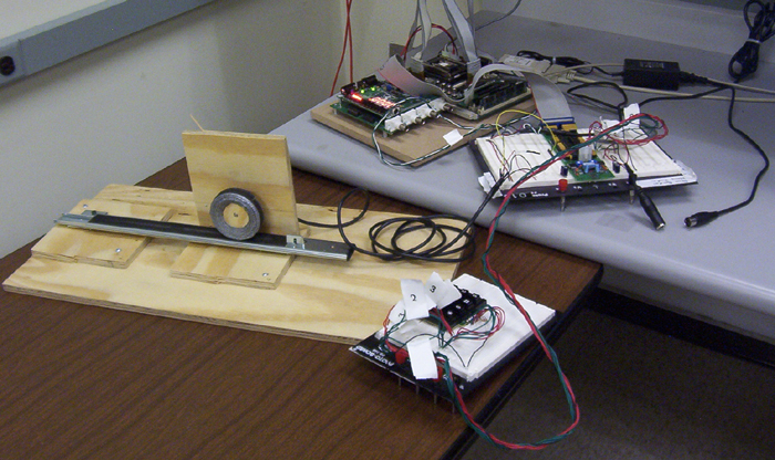
The complete system: slider, keypad, project expansion board (with MIDI and footswitch connectors), and MPC823 and Xilinx FPGA board.
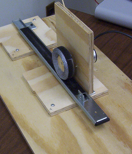
One side of the slider, showing wheel and friction tape junction.
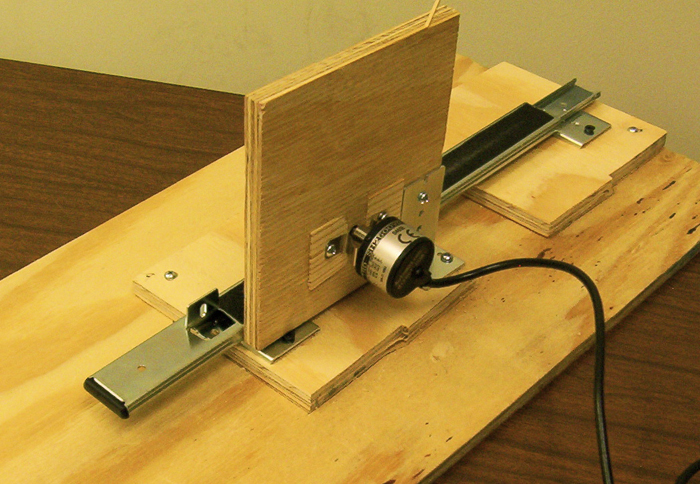
Other side of slider, showing quadrature encoder.
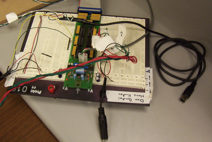
Project expansion board with MIDI and footswitch connectors, keypad connection, and quadrature encoder connnection.
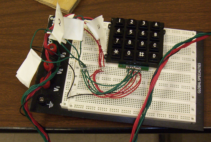
Keypad with connection to project expansion board.
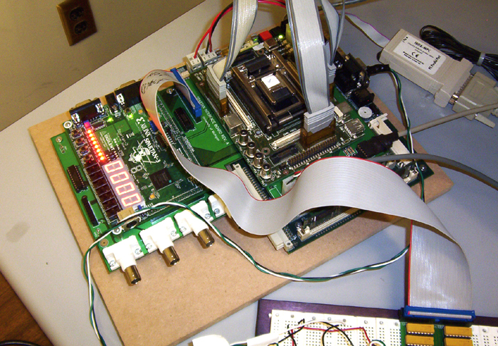
MPC823 and Xilinx FPGA board, showing serial MIDI connection from processor.
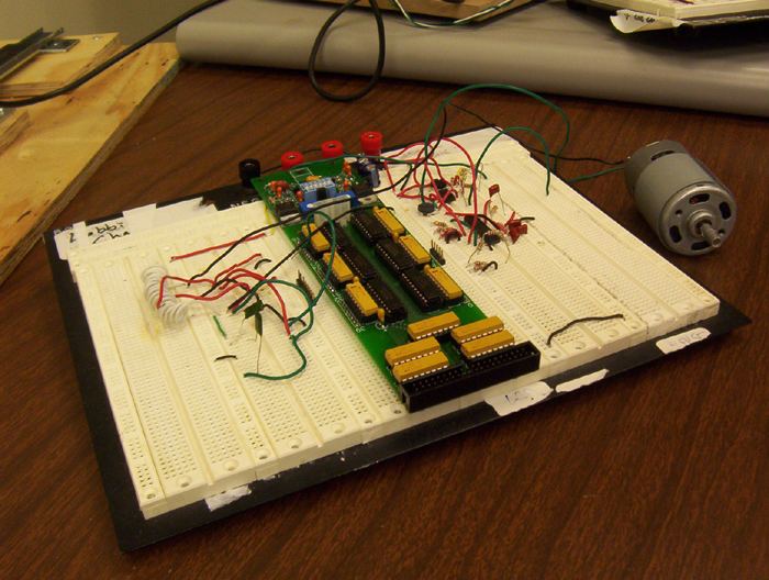
Motor control circuitry, including H-bridge, PWM controller, and DC motor. Not used in final implementation.
[ Back to top ]