Three Card Poker
EECS 373 W'06
Group Members: Geoff Thill & Anthony Gorski
Introduction
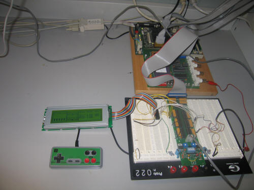
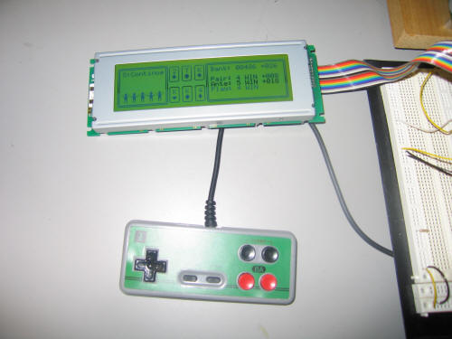
When we were assigned to do this project, we both wanted to create some type of game. We looked over some of the other projects, and no one had done Three Card Poker so we decided to go with it. Our final system has the game play displayed on an Optrex graphics LCD and the play is controlled via a Nintendo 8 controller. We found infinite possibilities exist for creating the graphics for the game, however due to time constraints, we kept it fairly simple. Further details are explained later.
High Level Design
We were able to apply several of the skills from lab while designing our project. These include writing an ABI-compliant device driver for the Nintendo8 controller, controlling bus transactions in order to correctly transfer data across the bi-directional bus without any dispute, and software interrupts that are thrown when the player wins a hand.
The Nintendo8 controller detects button presses by latching them via one of its control lines and sending which button was pressed to the I/O Board. They are used as interrupts to run the software that controls the game. Without the button presses, the game will just sit in a waiting state.
The Optrex graphics display has several inputs and outputs. They are explained in great detail in the manufacturer's specification. In order to interact with the display, we needed to design a timing controller that would meet the required set-up and hold times required by the spec. We allocated the LCD space in memory, and then we are able to read the status and write data to it. We found that when trying to do anything with the LCD, we needed to write a sequence of instructions to it. In the end, this was all done in the software.
Member Task Distribution
Nintendo8 Controller Interface: Primarily Anthony
LCD Interface: Geoff & Anthony
Software (Game): Primarily Geoff
Both team members worked very closely on all project tasks mainly due to the fact that there aren't that many different components to work with. We focused first on the Nintendo8 controller and then the LCD. Both required hours and hours of debugging and that was performed by both of us equally.
Hardware Design
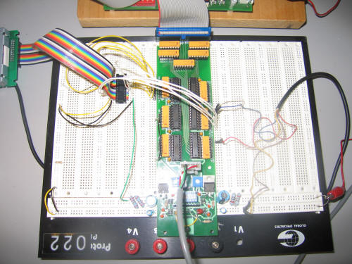
We integrated our design components into the schematic that we used for the labs. We created a module that was in charge of the Nintendo8 controller and one that was in charge of the LCD. Both of them used Verilog code to send the correct timing signals in the correct sequence. This was basically designed using flip-flops and assigning such things as TA_BAR and RD_WR_EN. The Nintendo8 controller needed a clock divider in order to slow down the rate at which it would sample data. We also found that when the player presses a button, we only need to detect it the first time, and after that we need to stop throwing the interrupt (as to avoid telling the processor that the button was pressed 50 times when it was only pressed once). To do this, when we detected that it was pressed, we had the hardware remember that and if on the previous sample a button was pressed, it would not assert another press. It would wait for the button to be in its initial state before it would detect and assert another button press.
Software Design
Our software is what really makes our game work. It is the glue that holds all of the individual components together. It is in charge of reading the status of both the LCD and the controller. It is where the game itself exists. Following is an attempt to give the reader an idea of the program flow.
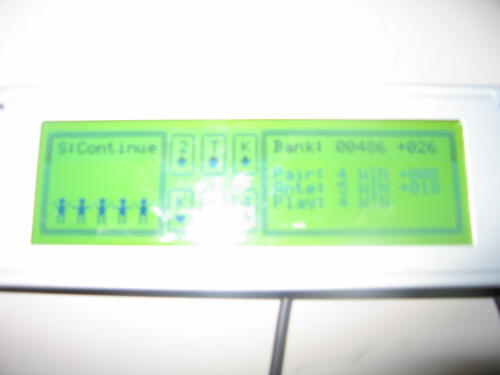
First of all, every time that we want to write or read to the LCD, we have to do a Status Read. We created a function that is a set of instruction that does this for us. It returns the status of the 20-pin set that interfaces the LCD to the I/O board. Writing to the LCD is not an easy task in itself at all. It requires a specific sequence of instructions and any minor error will prevent the write from going through. We have several different functions that take in arguments like what we want displayed and where we want it displayed, and they act appropriately. We call these throughout the program to print out the player's bank, the different bets, and the cards. More specifically, we have a function that does character writes, and we have a function that does graphic rights. The graphic writes come from the section of our program where we define different bit sequences in order to display things like the suit of the cards and the dancers that appear when the player wins.
The program starts out initializing the device drivers in assembly. It then calls the C function where the main game loop lies. It will stay in the main loop until an interrupt is thrown and it then branches to the ISR in assembly. At various points, it will call on assembly code to communicate with the I/O board and read and write the LCD.
Results of the Design
Our final product was very much the exact product we initially set out to design. We were able to work out any problems that we came across along the way through debugging. Quite simply put, if we had any problem with our final design, it would not be functional at all. We are very happy with the final integration of our game. Had we more time to work on it, we could have integrating sound components into the game, but this would just be in the category of "bells and whistles."
Conclusions
We have arrived at the conclusion that we were fully successful in implementing our initial design. The components that we used worked as they should, although there were times that we didn't believe that was the case! If we were going to do it over again, we would be smarter as far as debugging issues go. We would be able to find and debug problems more quickly because we believe that we have seen them all. This would allow us more time to expand our design.
To advise someone else on doing something similar, we would like to emphasize the importance of reading and understanding the manufacturer's specifications. Hooking everything up to the I/O board was pretty straightforward, the hard part was the software. There are initialization sequences on the 373 website that are very helpful in getting used to communicating with the LCD. Good luck!
Acknowledgements
We would like to thank Professor Brehob, Matt Smith, Matt Fornero, and Jeff Sterniak for their help and support throughout the semester.
References
Hardware
Main Schematic
LCD Macro
LCD Macro Controller
Nintendo Macro
Synthesized Bit File
Software
Main Assembly Program
Main Assembly Memory Layout
Main C Code
Controller References
EECS 270 Nintendo Controller Lab
LCD References
Manufacturer's Specification
T6963 Application Note
Helpful Hints by Jeff